Search results for: “hdr”


  • , ,

    HDR and Color

    https://www.soundandvision.com/content/nits-and-bits-hdr-and-color

    In HD we often refer to the range of available colors as a color gamut. Such a color gamut is typically plotted on a two-dimensional diagram, called a CIE chart, as shown in at the top of this blog. Each color is characterized by its x/y coordinates.

    Good enough for government work, perhaps. But for HDR, with its higher luminance levels and wider color, the gamut becomes three-dimensional.

    For HDR the color gamut therefore becomes a characteristic we now call the color volume. It isn’t easy to show color volume on a two-dimensional medium like the printed page or a computer screen, but one method is shown below. As the luminance becomes higher, the picture eventually turns to white. As it becomes darker, it fades to black. The traditional color gamut shown on the CIE chart is simply a slice through this color volume at a selected luminance level, such as 50%.

    Three different color volumes—we still refer to them as color gamuts though their third dimension is important—are currently the most significant. The first is BT.709 (sometimes referred to as Rec.709), the color gamut used for pre-UHD/HDR formats, including standard HD.

    The largest is known as BT.2020; it encompasses (roughly) the range of colors visible to the human eye (though ET might find it insufficient!).

    Between these two is the color gamut used in digital cinema, known as DCI-P3.

    sRGB

    D65


  • ,

    Finn Jager – From HEIC (High Efficiency Image Container) iPhone to a Multichannel EXR

    Finn Jäger has spent some time in making a sleeker tool for all you VFX nerds out there, it takes a HEIC iPhone still and exports a Multichannel EXR – the cool thing is it also converts it to acesCG and it merges the SDR base image with the gain map according to apples math hdr_rgb = sdr_rgb * (1.0 + (headroom – 1.0) * gainmap)

    https://github.com/finnschi/heic-shenanigans

  • ,

    Romain Chauliac – LightIt a lighting script for Maya and Arnold

    LightIt is a script for Maya and Arnold that will help you and improve your lighting workflow.
    Thanks to preset studio lighting components (lights, backdrop…), high quality studio scenes and HDRI library manager.


    https://www.artstation.com/artwork/393emJ


    https://wzx.gumroad.com/l/lightit

  • ,

    Image rendering bit depth

    The terms 8-bit, 16-bit, 16-bit float, and 32-bit refer to different data formats used to store and represent image information, as bits per pixel.


    https://en.wikipedia.org/wiki/Color_depth


    In color technology, color depth also known as bit depth, is either the number of bits used to indicate the color of a single pixel, OR the number of bits used for each color component of a single pixel.


    When referring to a pixel, the concept can be defined as bits per pixel (bpp).


    When referring to a color component, the concept can be defined as bits per component, bits per channel, bits per color (all three abbreviated bpc), and also bits per pixel component, bits per color channel or bits per sample (bps). Modern standards tend to use bits per component, but historical lower-depth systems used bits per pixel more often.


    Color depth is only one aspect of color representation, expressing the precision with which the amount of each primary can be expressed; the other aspect is how broad a range of colors can be expressed (the gamut). The definition of both color precision and gamut is accomplished with a color encoding specification which assigns a digital code value to a location in a color space.


    Here’s a simple explanation of each.


    8-bit images (i.e. 24 bits per pixel for a color image) are considered Low Dynamic Range.
    They can store around 5 stops of light and each pixel carry a value from 0 (black) to 255 (white).
    As a comparison, DSLR cameras can capture ~12-15 stops of light and they use RAW files to store the information.


    16-bit: This format is commonly referred to as “half-precision.” It uses 16 bits of data to represent color values for each pixel. With 16 bits, you can have 65,536 discrete levels of color, allowing for relatively high precision and smooth gradients. However, it has a limited dynamic range, meaning it cannot accurately represent extremely bright or dark values. It is commonly used for regular images and textures.


    16-bit float: This format is an extension of the 16-bit format but uses floating-point numbers instead of fixed integers. Floating-point numbers allow for more precise calculations and a larger dynamic range. In this case, the 16 bits are used to store both the color value and the exponent, which controls the range of values that can be represented. The 16-bit float format provides better accuracy and a wider dynamic range than regular 16-bit, making it useful for high-dynamic-range imaging (HDRI) and computations that require more precision.


    32-bit: (i.e. 96 bits per pixel for a color image) are considered High Dynamic Range. This format, also known as “full-precision” or “float,” uses 32 bits to represent color values and offers the highest precision and dynamic range among the three options. With 32 bits, you have a significantly larger number of discrete levels, allowing for extremely accurate color representation, smooth gradients, and a wide range of brightness values. It is commonly used for professional rendering, visual effects, and scientific applications where maximum precision is required.


    Bits and HDR coverage

    High Dynamic Range (HDR) images are designed to capture a wide range of luminance values, from the darkest shadows to the brightest highlights, in order to reproduce a scene with more accuracy and detail. The bit depth of an image refers to the number of bits used to represent each pixel’s color information. When comparing 32-bit float and 16-bit float HDR images, the drop in accuracy primarily relates to the precision of the color information.


    A 32-bit float HDR image offers a higher level of precision compared to a 16-bit float HDR image. In a 32-bit float format, each color channel (red, green, and blue) is represented by 32 bits, allowing for a larger range of values to be stored. This increased precision enables the image to retain more details and subtleties in color and luminance.


    On the other hand, a 16-bit float HDR image utilizes 16 bits per color channel, resulting in a reduced range of values that can be represented. This lower precision leads to a loss of fine details and color nuances, especially in highly contrasted areas of the image where there are significant differences in luminance.


    The drop in accuracy between 32-bit and 16-bit float HDR images becomes more noticeable as the exposure range of the scene increases. Exposure range refers to the span between the darkest and brightest areas of an image. In scenes with a limited exposure range, where the luminance differences are relatively small, the loss of accuracy may not be as prominent or perceptible. These images usually are around 8-10 exposure levels.


    However, in scenes with a wide exposure range, such as a landscape with deep shadows and bright highlights, the reduced precision of a 16-bit float HDR image can result in visible artifacts like color banding, posterization, and loss of detail in both shadows and highlights. The image may exhibit abrupt transitions between tones or colors, which can appear unnatural and less realistic.


    To provide a rough estimate, it is often observed that exposure values beyond approximately ±6 to ±8 stops from the middle gray (18% reflectance) may be more prone to accuracy issues in a 16-bit float format. This range may vary depending on the specific implementation and encoding scheme used.


    To summarize, the drop in accuracy between 32-bit and 16-bit float HDR images is mainly related to the reduced precision of color information. This decrease in precision becomes more apparent in scenes with a wide exposure range, affecting the representation of fine details and leading to visible artifacts in the image.


    In practice, this means that exposure values beyond a certain range will experience a loss of accuracy and detail when stored in a 16-bit float format. The exact range at which this loss occurs depends on the encoding scheme and the specific implementation. However, in general, extremely bright or extremely dark values that fall outside the representable range may be subject to quantization errors, resulting in loss of detail, banding, or other artifacts.


    HDRs used for lighting purposes are usually slightly convolved to improve on sampling speed and removing specular artefacts. To that extent, 16 bit float HDRIs tend to me most used in CG cycles.


  • ,

    RICOH THETA Z1 51GB camera – 360° images in RAW format

    https://theta360.com/en/about/theta/z1.html


    • 23MP(6720 x 3360, 7K)
    • superior noise reduction performance
    • F2.1, F3.5 and F5.6
    • 4K videos (3840 x 1920, 29.97fps)
    • RAW (DNG) image format
    • 360° live streaming in 4K
    • record sound from 4 different directions when shooting video
    • editing of 360° images in Adobe Photoshop Lightroom Classic CC
    • Android™ base system for the OS. Use plug-ins to customize your own THETA.
    • Wireless 2.4 GHz: 1 to 11ch or 1 to 13ch
    • Wireless 5 GHz: W52 (36 to 48ch, channel bandwidth 20/40/80 MHz supported)


    Theta Z1 is Ricoh’s flagship 360 camera that features 1-inch sensors, which are the largest available for dual lens 360 cameras.  It has been a highly regarded camera among 360 photographers because of its excellent image quality, color accuracy, and its ability to shoot Raw DNG photos with exceptional exposure latitude.


    Bracketing mode 2022

    Rquirement: Basic app iOS ver.2.20.0, Android ver.2.5.0, Camera firmware ver.2.10.3

    https://community.theta360.guide/t/new-feature-ae-bracket-added-in-the-shooting-mode-z1-only/8247


    HDRi for VFX

    https://community.theta360.guide/t/create-high-quality-hdri-for-vfx-using-ricoh-theta-z1/4789/4


    ND filtering


    https://community.theta360.guide/t/neutral-density-solution-for-most-theta-cameras/7331


    https://community.theta360.guide/t/long-exposure-nd-filter-for-ricoh-theta/1100

  • , ,

    LUX vs LUMEN vs NITS vs CANDELA – What is the difference

    More details here: Lumens vs Candelas (candle) vs Lux vs FootCandle vs Watts vs Irradiance vs Illuminance


    https://www.inhouseav.com.au/blog/beginners-guide-nits-lumens-brightness/


    Candela


    Candela is the basic unit of measure of the entire volume of light intensity from any point in a single direction from a light source. Note the detail: it measures the total volume of light within a certain beam angle and direction.
    While the luminance of starlight is around 0.001 cd/m2, that of a sunlit scene is around 100,000 cd/m2, which is a hundred millions times higher. The luminance of the sun itself is approximately 1,000,000,000 cd/m2.


    NIT


    https://en.wikipedia.org/wiki/Candela_per_square_metre


    The candela per square metre (symbol: cd/m2) is the unit of luminance in the International System of Units (SI). The unit is based on the candela, the SI unit of luminous intensity, and the square metre, the SI unit of area. The nit (symbol: nt) is a non-SI name also used for this unit (1 nt = 1 cd/m2).[1] The term nit is believed to come from the Latin word nitēre, “to shine”. As a measure of light emitted per unit area, this unit is frequently used to specify the brightness of a display device.

    NIT and cd/m2 (candela power) represent the same thing and can be used interchangeably. One nit is equivalent to one candela per square meter, where the candela is the amount of light which has been emitted by a common tallow candle, but NIT is not part of the International System of Units (abbreviated SI, from Systeme International, in French).

    It’s easiest to think of a TV as emitting light directly, in much the same way as the Sun does. Nits are simply the measurement of the level of light (luminance) in a given area which the emitting source sends to your eyes or a camera sensor.

    The Nit can be considered a unit of visible-light intensity which is often used to specify the brightness level of an LCD.

    1 Nit is approximately equal to 3.426 Lumens. To work out a comparable number of Nits to Lumens, you need to multiply the number of Nits by 3.426. If you know the number of Lumens, and wish to know the Nits, simply divide the number of Lumens by 3.426.

    Most consumer desktop LCDs have Nits of 200 to 300, the average TV most likely has an output capability of between 100 and 200 Nits, and an HDR TV ranges from 400 to 1,500 Nits.
    Virtual Production sets currently sport around 6000 NIT ceiling and 1000 NIT wall panels.


    The ambient brightness of a sunny day with clear blue skies is between 7000-10,000 nits (between 3000-7000 nits for overcast skies and indirect sunlight).
    A bright sunny day can have specular highlights that reach over 100,000 nits. Direct sunlight is around 1,600,000,000 nits.
    10,000 nits is also the typical brightness of a fluorescent tube – bright, but not painful to look at.


    https://www.displaydaily.com/article/display-daily/dolby-vision-vs-hdr10-clarified

    Tests showed that a “black level” of 0.005 nits (cd/m²) satisfied the vast majority of viewers. While 0.005 nits is very close to true black, Griffis says Dolby can go down to a black of 0.0001 nits, even though there is no need or ability for displays to get that dark today.
    How bright is white? Dolby says the range of 0.005 nits – 10,000 nits satisfied 84% of the viewers in their viewing tests.
    The brightest consumer HDR displays today are about 1,500 nits. Professional displays where HDR content is color-graded can achieve up to 4,000 nits peak brightness.

    High brightness that would be in danger of damaging the eye would be in the neighborhood of 250,000 nits.


    Lumens


    Lumen is a measure of how much light is emitted (luminance, luminous flux) by an object. It indicates the total potential amount of light from a light source that is visible to the human eye.
    Lumen is commonly used in the context of light bulbs or video-projectors as a metric for their brightness power.

    Lumen is used to describe light output, and about video projectors, it is commonly referred to as ANSI Lumens. Simply put, lumens is how to find out how bright a LED display is. The higher the lumens, the brighter to display!

    Technically speaking, a Lumen is the SI unit of luminous flux, which is equal to the amount of light which is emitted per second in a unit solid angle of one steradian from a uniform source of one-candela intensity radiating in all directions.


    LUX


    Lux (lx) or often Illuminance, is a photometric unit along a given area, which takes in account the sensitivity of human eye to different wavelenghts. It is the measure of light at a specific distance within a specific area at that distance. Often used to measure the incidental sun’s intensity.


  • , ,

    StudioBinder.com – Photography basics: What is Dynamic Range in Photography

    https://www.studiobinder.com/blog/what-is-dynamic-range-photography/


    https://www.hdrsoft.com/resources/dri.html#bit-depth


    The dynamic range is a ratio between the maximum and minimum values of a physical measurement. Its definition depends on what the dynamic range refers to.

    For a scene: Dynamic range is the ratio between the brightest and darkest parts of the scene.


    For a camera: Dynamic range is the ratio of saturation to noise. More specifically, the ratio of the intensity that just saturates the camera to the intensity that just lifts the camera response one standard deviation above camera noise.


    For a display: Dynamic range is the ratio between the maximum and minimum intensities emitted from the screen.


  • , , ,

    Types of Film Lights and their efficiency – CRI, Color Temperature and Luminous Efficacy

    nofilmschool.com/types-of-film-lights


    “Not every light performs the same way. Lights and lighting are tricky to handle. You have to plan for every circumstance. But the good news is, lighting can be adjusted. Let’s look at different factors that affect lighting in every scene you shoot. ”

    Use CRI, Luminous Efficacy and color temperature controls to match your needs.


    Color Temperature
    Color temperature describes the “color” of white light by a light source radiated by a perfect black body at a given temperature measured in degrees Kelvin


    https://www.pixelsham.com/2019/10/18/color-temperature/


    CRI
    “The Color Rendering Index is a measurement of how faithfully a light source reveals the colors of whatever it illuminates, it describes the ability of a light source to reveal the color of an object, as compared to the color a natural light source would provide. The highest possible CRI is 100. A CRI of 100 generally refers to a perfect black body, like a tungsten light source or the sun. ”


    https://www.studiobinder.com/blog/what-is-color-rendering-index/


    https://en.wikipedia.org/wiki/Color_rendering_index


    Light source CCT (K) CRI
    Low-pressure sodium (LPS/SOX) 1800 −44
    Clear mercury-vapor 6410 17
    High-pressure sodium (HPS/SON) 2100 24
    Coated mercury-vapor 3600 49
    Halophosphate warm-white fluorescent 2940 51
    Halophosphate cool-white fluorescent 4230 64
    Tri-phosphor warm-white fluorescent 2940 73
    Halophosphate cool-daylight fluorescent 6430 76
    “White” SON 2700 82
    Standard LED Lamp 2700–5000 83
    Quartz metal halide 4200 85
    Tri-phosphor cool-white fluorescent 4080 89
    High-CRI LED lamp (blue LED) 2700–5000 95
    Ceramic discharge metal-halide lamp 5400 96
    Ultra-high-CRI LED lamp (violet LED) 2700–5000 99
    Incandescent/halogen bulb 3200 100


    Luminous Efficacy
    Luminous efficacy is a measure of how well a light source produces visible light, watts out versus watts in, measured in lumens per watt. In other words it is a measurement that indicates the ability of a light source to emit visible light using a given amount of power. It is a ratio of the visible energy to the power that goes into the bulb.


    FILM LIGHT TYPES

    https://www.studiobinder.com/blog/video-lighting-kits/?utm_campaign=Weekly_Newsletter&utm_medium=email&utm_source=sendgrid&utm_term=production-lighting&utm_content=production-lighting


    Consumer light types


    https://www.researchgate.net/figure/Emission-spectra-of-different-light-sources-a-incandescent-tungsten-light-bulb-b_fig1_312320039


    http://dev.informationdisplay.org/IDArchive/2015/NovemberDecember/FrontlineTechnologyCandleLikeEmission.aspx


    Tungsten Lights
    Light interiors and match domestic places or office locations. Daylight.

    Advantages of Tungsten Lights
    Almost perfect color rendition
    Low cost
    Does not use mercury like CFLs (fluorescent) or mercury vapor lights
    Better color temperature than standard tungsten
    Longer life than a conventional incandescent
    Instant on to full brightness, no warm-up time, and it is dimmable

    Disadvantages of Tungsten Lights
    Extremely hot
    High power requirement
    The lamp is sensitive to oils and cannot be touched
    The bulb is capable of blowing and sending hot glass shards outward. A screen or layer of glass on the outside of the lamp can protect users.


    Hydrargyrum medium-arc iodide lights
    HMI’s are used when high output is required. They are also used to recreate sun shining through windows or to fake additional sun while shooting exteriors. HMIs can light huge areas at once.

    Advantages of HMI lights
    High light output
    Higher efficiency
    High color temperature

    Disadvantages of HMI lights:
    High cost
    High power requirement
    Dims only to about 50%
    the color temperature increases with dimming
    HMI bulbs will explode is dropped and release toxic chemicals


    Fluorescent
    Fluorescent film lighting is achieved by laying multiple tubes next to each other, combining as many as you want for the desired brightness. The good news is you can choose your bulbs to either be warm or cool depending on the scenario you’re shooting. You want to get these bulbs close to the subject because they’re not great at opening up spaces. Fluorescent lighting is used to light interiors and is more compact and cooler than tungsten or HMI lighting.

    Advantages of Fluorescent lights
    High efficiency
    Low power requirement
    Low cost
    Long lamp life
    Cool
    Capable of soft even lighting over a large area
    Lightweight

    Disadvantages of Fluorescent lights
    Flicker
    High CRI
    Domestic tubes have low CRI & poor color rendition.


    LED
    LED’s are more and more common on film sets. You can use batteries to power them. That makes them portable and sleek – no messy cabled needed. You can rig your own panels of LED lights to fit any space necessary as well. LED’s can also power Fresnel style lamp heads such as the Arri L-series.

    Advantages of LED light
    Soft, even lighting
    Pure light without UV-artifacts
    High efficiency
    Low power consumption, can be battery powered
    Excellent dimming by means of pulse width modulation control
    Long lifespan
    Environmentally friendly
    Insensitive to shock
    No risk of explosion

    Disadvantages of LED light
    High cost.
    LED’s are currently still expensive for their total light output

    (more…)

  • Outpost VFX lighting tips

    www.outpost-vfx.com/en/news/18-pro-tips-and-tricks-for-lighting


    Get as much information regarding your plate lighting as possible

    • Always use a reference
    • Replicate what is happening in real life
    • Invest into a solid HDRI
    • Start Simple
    • Observe real world lighting, photography and cinematography
    • Don’t neglect the theory
    • Learn the difference between realism and photo-realism.
    • Keep your scenes organised


  • , , ,

    Advanced Computer Vision with Python OpenCV and Mediapipe

    https://www.freecodecamp.org/news/advanced-computer-vision-with-python


    https://www.freecodecamp.org/news/how-to-use-opencv-and-python-for-computer-vision-and-ai


    Working for a VFX (Visual Effects) studio provides numerous opportunities to leverage the power of Python and OpenCV for various tasks. OpenCV is a versatile computer vision library that can be applied to many aspects of the VFX pipeline. Here’s a detailed list of opportunities to take advantage of Python and OpenCV in a VFX studio:


    1. Image and Video Processing:
      • Preprocessing: Python and OpenCV can be used for tasks like resizing, color correction, noise reduction, and frame interpolation to prepare images and videos for further processing.
      • Format Conversion: Convert between different image and video formats using OpenCV’s capabilities.
    2. Tracking and Matchmoving:
      • Feature Detection and Tracking: Utilize OpenCV to detect and track features in image sequences, which is essential for matchmoving tasks to integrate computer-generated elements into live-action footage.
    3. Rotoscoping and Masking:
      • Segmentation and Masking: Use OpenCV for creating and manipulating masks and alpha channels for various VFX tasks, like isolating objects or characters from their backgrounds.
    4. Camera Calibration:
      • Intrinsic and Extrinsic Calibration: Python and OpenCV can help calibrate cameras for accurate 3D scene reconstruction and camera tracking.
    5. 3D Scene Reconstruction:
      • Stereoscopy: Use OpenCV to process stereoscopic image pairs for creating 3D depth maps and generating realistic 3D scenes.
      • Structure from Motion (SfM): Implement SfM techniques to create 3D models from 2D image sequences.
    6. Green Screen and Blue Screen Keying:
      • Chroma Keying: Implement advanced keying algorithms using OpenCV to seamlessly integrate actors and objects into virtual environments.
    7. Particle and Fluid Simulations:
      • Particle Tracking: Utilize OpenCV to track and manipulate particles in fluid simulations for more realistic visual effects.
    8. Motion Analysis:
      • Optical Flow: Implement optical flow algorithms to analyze motion patterns in footage, useful for creating dynamic VFX elements that follow the motion of objects.
    9. Virtual Set Extension:
      • Camera Projection: Use camera calibration techniques to project virtual environments onto physical sets, extending the visual scope of a scene.
    10. Color Grading:
      • Color Correction: Implement custom color grading algorithms to match the color tones and moods of different shots.
    11. Automated QC (Quality Control):
      • Artifact Detection: Develop Python scripts to automatically detect and flag visual artifacts like noise, flicker, or compression artifacts in rendered frames.
    12. Data Analysis and Visualization:
      • Performance Metrics: Use Python to analyze rendering times and optimize the rendering process.
      • Data Visualization: Generate graphs and charts to visualize render farm usage, project progress, and resource allocation.
    13. Automating Repetitive Tasks:
      • Batch Processing: Automate repetitive tasks like resizing images, applying filters, or converting file formats across multiple shots.
    14. Machine Learning Integration:
      • Object Detection: Integrate machine learning models (using frameworks like TensorFlow or PyTorch) to detect and track specific objects or elements within scenes.
    15. Pipeline Integration:
      • Custom Tools: Develop Python scripts and tools to integrate OpenCV-based processes seamlessly into the studio’s pipeline.
    16. Real-time Visualization:
      • Live Previsualization: Implement real-time OpenCV-based visualizations to aid decision-making during the preproduction stage.
    17. VR and AR Integration:
      • Augmented Reality: Use Python and OpenCV to integrate virtual elements into real-world footage, creating compelling AR experiences.
    18. Camera Effects:
      • Lens Distortion: Correct lens distortions and apply various camera effects using OpenCV, contributing to the desired visual style.


    Interpolating frames from an EXR sequence using OpenCV can be useful when you have only every second frame of a final render and you want to create smoother motion by generating intermediate frames. However, keep in mind that interpolating frames might not always yield perfect results, especially if there are complex changes between frames. Here’s a basic example of how you might use OpenCV to achieve this:


    import cv2
    import numpy as np
    import os
    
    # Replace with the path to your EXR frames
    exr_folder = "path_to_exr_frames"
    
    # Replace with the appropriate frame extension and naming convention
    frame_template = "frame_{:04d}.exr"
    
    # Define the range of frame numbers you have
    start_frame = 1
    end_frame = 100
    step = 2
    
    # Define the output folder for interpolated frames
    output_folder = "output_interpolated_frames"
    os.makedirs(output_folder, exist_ok=True)
    
    # Loop through the frame range and interpolate
    for frame_num in range(start_frame, end_frame + 1, step):
        frame_path = os.path.join(exr_folder, frame_template.format(frame_num))
        next_frame_path = os.path.join(exr_folder, frame_template.format(frame_num + step))
    
        if os.path.exists(frame_path) and os.path.exists(next_frame_path):
            frame = cv2.imread(frame_path, cv2.IMREAD_ANYDEPTH | cv2.IMREAD_COLOR)
            next_frame = cv2.imread(next_frame_path, cv2.IMREAD_ANYDEPTH | cv2.IMREAD_COLOR)
    
            # Interpolate frames using simple averaging
            interpolated_frame = (frame + next_frame) / 2
    
            # Save interpolated frame
            output_path = os.path.join(output_folder, frame_template.format(frame_num))
            cv2.imwrite(output_path, interpolated_frame)
    
            print(f"Interpolated frame {frame_num}") # alternatively: print("Interpolated frame {}".format(frame_num))


    Please note the following points:


    • The above example uses simple averaging to interpolate frames. More advanced interpolation methods might provide better results, such as motion-based algorithms like optical flow-based interpolation.
    • EXR files can store high dynamic range (HDR) data, so make sure to use cv2.IMREAD_ANYDEPTH flag when reading these files.
    • OpenCV might not support EXR format directly. You might need to use a library like exr to read and manipulate EXR files, and then convert them to OpenCV-compatible formats.
    • Consider the characteristics of your specific render when using interpolation. If there are large changes between frames, the interpolation might lead to artifacts.
    • Experiment with different interpolation methods and parameters to achieve the desired result.
    • For a more advanced and accurate interpolation, you might need to implement or use existing algorithms that take into account motion estimation and compensation.


  • Monitor Color Calibration Probes – Datacolor SpyderX vs X-Rite i1Display Pro Plus

    https://www.amazon.ca/dp/B0076A620Y

    Datacolor SpyderX Elite
    This excellent monitor calibrator comes with useful features, such as multi-monitor and projectors support, and it can detect the light conditions you’re working in to ensure your monitor looks its best.

    X-Rite i1Display Pro Plus
    Supports multiple monitors and HDR.
    You’re able to use your profile across multiple displays (either on the same machine or network) as well as assess the ambient light in your workspace to set your monitor up for best results.

    https://www.amazon.ca/X-Rite-i1Display-Pro-Plus-EODIS3PL/dp/B07XFX74V6


  • , ,

    Photography basics: Exposure Value vs Photographic Exposure vs Il/Luminance vs Pixel luminance measurements

    Also see: https://www.pixelsham.com/2015/05/16/how-aperture-shutter-speed-and-iso-affect-your-photos/


    In photography, exposure value (EV) is a number that represents a combination of a camera’s shutter speed and f-number, such that all combinations that yield the same exposure have the same EV (for any fixed scene luminance).


    The EV concept was developed in an attempt to simplify choosing among combinations of equivalent camera settings. Although all camera settings with the same EV nominally give the same exposure, they do not necessarily give the same picture. EV is also used to indicate an interval on the photographic exposure scale. 1 EV corresponding to a standard power-of-2 exposure step, commonly referred to as a stop


    EV 0 corresponds to an exposure time of 1 sec and a relative aperture of f/1.0. If the EV is known, it can be used to select combinations of exposure time and f-number.


    https://www.streetdirectory.com/travel_guide/141307/photography/exposure_value_ev_and_exposure_compensation.html

    Note EV does not equal to photographic exposure. Photographic Exposure is defined as how much light hits the camera’s sensor. It depends on the camera settings mainly aperture and shutter speed. Exposure value (known as EV) is a number that represents the exposure setting of the camera.


    Thus, strictly, EV is not a measure of luminance (indirect or reflected exposure) or illuminance (incidental exposure); rather, an EV corresponds to a luminance (or illuminance) for which a camera with a given ISO speed would use the indicated EV to obtain the nominally correct exposure. Nonetheless, it is common practice among photographic equipment manufacturers to express luminance in EV for ISO 100 speed, as when specifying metering range or autofocus sensitivity.


    The exposure depends on two things: how much light gets through the lenses to the camera’s sensor and for how long the sensor is exposed. The former is a function of the aperture value while the latter is a function of the shutter speed. Exposure value is a number that represents this potential amount of light that could hit the sensor. It is important to understand that exposure value is a measure of how exposed the sensor is to light and not a measure of how much light actually hits the sensor. The exposure value is independent of how lit the scene is. For example a pair of aperture value and shutter speed represents the same exposure value both if the camera is used during a very bright day or during a dark night.


    Each exposure value number represents all the possible shutter and aperture settings that result in the same exposure. Although the exposure value is the same for different combinations of aperture values and shutter speeds the resulting photo can be very different (the aperture controls the depth of field while shutter speed controls how much motion is captured).

    EV 0.0 is defined as the exposure when setting the aperture to f-number 1.0 and the shutter speed to 1 second. All other exposure values are relative to that number. Exposure values are on a base two logarithmic scale. This means that every single step of EV – plus or minus 1 – represents the exposure (actual light that hits the sensor) being halved or doubled.

    https://www.streetdirectory.com/travel_guide/141307/photography/exposure_value_ev_and_exposure_compensation.html


    Formula

    https://en.wikipedia.org/wiki/Exposure_value


    https://www.scantips.com/lights/math.html


    which means   2EV = N² / t

    where

    • N is the relative aperture (f-number) Important: Note that f/stop values must first be squared in most calculations
    • t is the exposure time (shutter speed) in seconds

    EV 0 corresponds to an exposure time of 1 sec and an aperture of f/1.0.

    Example: If f/16 and 1/4 second, then this is:

    (N² / t) = (16 × 16 ÷ 1/4) = (16 × 16 × 4) = 1024.

    Log₂(1024) is EV 10. Meaning, 210 = 1024.


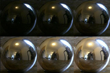
    Collecting photographic exposure using Light Meters

    https://photo.stackexchange.com/questions/968/how-can-i-correctly-measure-light-using-a-built-in-camera-meter

    The exposure meter in the camera does not know whether the subject itself is bright or not. It simply measures the amount of light that comes in, and makes a guess based on that. The camera will aim for 18% gray, meaning if you take a photo of an entirely white surface, and an entirely black surface you should get two identical images which both are gray (at least in theory)

    https://en.wikipedia.org/wiki/Light_meter

    For reflected-light meters, camera settings are related to ISO speed and subject luminance by the reflected-light exposure equation:

    where

    • N is the relative aperture (f-number)
    • t is the exposure time (“shutter speed”) in seconds
    • L is the average scene luminance
    • S is the ISO arithmetic speed
    • K is the reflected-light meter calibration constant


    For incident-light meters, camera settings are related to ISO speed and subject illuminance by the incident-light exposure equation:

    where

    • E is the illuminance (in lux)
    • C is the incident-light meter calibration constant


    Two values for K are in common use: 12.5 (Canon, Nikon, and Sekonic) and 14 (Minolta, Kenko, and Pentax); the difference between the two values is approximately 1/6 EV.
    For C a value of 250 is commonly used.


    Nonetheless, it is common practice among photographic equipment manufacturers to also express luminance in EV for ISO 100 speed. Using K = 12.5, the relationship between EV at ISO 100 and luminance L is then :

    L = 2(EV-3)


    The situation with incident-light meters is more complicated than that for reflected-light meters, because the calibration constant C depends on the sensor type. Illuminance is measured with a flat sensor; a typical value for C is 250 with illuminance in lux. Using C = 250, the relationship between EV at ISO 100 and illuminance E is then :


    E = 2.5 * 2(EV)


    https://nofilmschool.com/2018/03/want-easier-and-faster-way-calculate-exposure-formula

    Three basic factors go into the exposure formula itself instead: aperture, shutter, and ISO. Plus a light meter calibration constant.

    f-stop²/shutter (in seconds) = lux * ISO/C


    If you at least know four of those variables, you’ll be able to calculate the missing value.

    So, say you want to figure out how much light you’re going to need in order to shoot at a certain f-stop. Well, all you do is plug in your values (you should know the f-stop, ISO, and your light meter calibration constant) into the formula below:

    lux = C (f-stop²/shutter (in seconds))/ISO


    Exposure Value Calculator:

    https://snapheadshots.com/resources/exposure-and-light-calculator


    https://www.scantips.com/lights/exposurecalc.html


    https://www.pointsinfocus.com/tools/exposure-settings-ev-calculator/#google_vignette


    From that perspective, an exposure stop is a measurement of Exposure and provides a universal linear scale to measure the increase and decrease in light, exposed to the image sensor, due to changes in shutter speed, iso & f-stop.
    +-1 stop is a doubling or halving of the amount of light let in when taking a photo.
    1 EV is just another way to say one stop of exposure change.


    One major use of EV (Exposure Value) is just to measure any change of exposure, where one EV implies a change of one stop of exposure. Like when we compensate our picture in the camera.


    If the picture comes out too dark, our manual exposure could correct the next one by directly adjusting one of the three exposure controls (f/stop, shutter speed, or ISO). Or if using camera automation, the camera meter is controlling it, but we might apply +1 EV exposure compensation (or +1 EV flash compensation) to make the result goal brighter, as desired. This use of 1 EV is just another way to say one stop of exposure change.


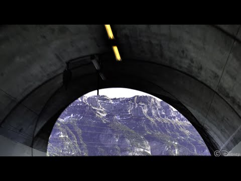
    On a perfect day the difference from sampling the sky vs the sun exposure with diffusing spot meters is about 3.2 exposure difference.

     ~15.4 EV for the sun
     ~12.2 EV for the sky
    

    That is as a ballpark. All still influenced by surroundings, accuracy parameters, fov of the sensor…


    EV calculator

    https://www.scantips.com/lights/evchart.html#calc

    http://www.fredparker.com/ultexp1.htm


    Exposure value is basically used to indicate an interval on the photographic exposure scale, with a difference of 1 EV corresponding to a standard power-of-2 exposure step, also commonly referred to as a “stop”.


    https://contrastly.com/a-guide-to-understanding-exposure-value-ev/


    Retrieving photographic exposure from an image

    All you can hope to measure with your camera and some images is the relative reflected luminance. Even if you have the camera settings. https://en.wikipedia.org/wiki/Relative_luminance


    If you REALLY want to know the amount of light in absolute radiometric units, you’re going to need to use some kind of absolute light meter or measured light source to calibrate your camera. For references on how to do this, see: Section 2.5 Obtaining Absolute Radiance from http://www.pauldebevec.com/Research/HDR/debevec-siggraph97.pdf


    IF you are still trying to gauge relative brightness, the level of the sun in Nuke can vary, but it should be in the thousands. Ie: between 30,000 and 65,0000 rgb value depending on time of the day, season and atmospherics.


    The values for a 12 o’clock sun, with the sun sampled at EV 15.5 (shutter 1/30, ISO 100, F22) is 32.000 RGB max values (or 32,000 pixel luminance).
    The thing to keep an eye for is the level of contrast between sunny side/fill side.  The terminator should be quite obvious,  there can be up to 3 stops difference between fill/key in sunny lit objects.


    Note: In Foundry’s Nuke, the software will map 18% gray to whatever your center f/stop is set to in the viewer settings (f/8 by default… change that to EV by following the instructions below).
    You can experiment with this by attaching an Exposure node to a Constant set to 0.18, setting your viewer read-out to Spotmeter, and adjusting the stops in the node up and down. You will see that a full stop up or down will give you the respective next value on the aperture scale (f8, f11, f16 etc.).
    One stop doubles or halves the amount or light that hits the filmback/ccd, so everything works in powers of 2.
    So starting with 0.18 in your constant, you will see that raising it by a stop will give you .36 as a floating point number (in linear space), while your f/stop will be f/11 and so on.

    If you set your center stop to 0 (see below) you will get a relative readout in EVs, where EV 0 again equals 18% constant gray.
    Note: make sure to set your Nuke read node to ‘raw data’


    In other words. Setting the center f-stop to 0 means that in a neutral plate, the middle gray in the macbeth chart will equal to exposure value 0. EV 0 corresponds to an exposure time of 1 sec and an aperture of f/1.0.


    To switch Foundry’s Nuke’s SpotMeter to return the EV of an image, click on the main viewport, and then press s, this opens the viewer’s properties. Now set the center f-stop to 0 in there. And the SpotMeter in the viewport will change from aperture and fstops to EV.


    If you are trying to gauge the EV from the pixel luminance in the image:
    – Setting the center f-stop to 0 means that in a neutral plate, the middle 18% gray will equal to exposure value 0.
    – So if EV 0 = 0.18 middle gray in nuke which equal to a pixel luminance of 0.18, doubling that value, doubles the EV.

    .18 pixel luminance = 0EV
    .36 pixel luminance = 1EV
    .72 pixel luminance = 2EV
    1.46 pixel luminance = 3EV
    ...


    This is a Geometric Progression function: xn = ar(n-1)

    The most basic example of this function is 1,2,4,8,16,32,… The sequence starts at 1 and doubles each time, so

    • a=1 (the first term)
    • r=2 (the “common ratio” between terms is a doubling)

    And we get:

    {a, ar, ar2, ar3, … }

    = {1, 1×2, 1×22, 1×23, … }

    = {1, 2, 4, 8, … }

    In this example the function translates to: n = 2(n-1)
    You can graph this curve through this expression: x = 2(y-1)  :

    You can go back and forth between the two values through a geometric progression function and a log function:

    (Note: in a spreadsheet this is: = POWER(2; cell# -1)  and  =LOG(cell#, 2)+1) )

    2(y-1) log2(x)+1
    x y
    1 1
    2 2
    4 3
    8 4
    16 5
    32 6
    64 7
    128 8
    256 9
    512 10
    1024 11
    2048 12
    4096 13


    Translating this into a geometric progression between an image pixel luminance and EV:

    (more…)

  • , , ,

    Photography basics: Lumens vs Candelas (candle) vs Lux vs FootCandle vs Watts vs Irradiance vs Illuminance

    https://www.translatorscafe.com/unit-converter/en-US/illumination/1-11/


    The power output of a light source is measured using the unit of watts W. This is a direct measure to calculate how much power the light is going to drain from your socket and it is not relatable to the light brightness itself.

    The amount of energy emitted from it per second. That energy comes out in a form of photons which we can crudely represent with rays of light coming out of the source. The higher the power the more rays emitted from the source in a unit of time.

    Not all energy emitted is visible to the human eye, so we often rely on photometric measurements, which takes in account the sensitivity of human eye to different wavelenghts


    Details in the post
    (more…)

  • , , ,

    Capturing textures albedo

    Building a Portable PBR Texture Scanner by Stephane Lb
    http://rtgfx.com/pbr-texture-scanner/


    How To Split Specular And Diffuse In Real Images, by John Hable
    http://filmicworlds.com/blog/how-to-split-specular-and-diffuse-in-real-images/


    Capturing albedo using a Spectralon
    https://www.activision.com/cdn/research/Real_World_Measurements_for_Call_of_Duty_Advanced_Warfare.pdf

    Real_World_Measurements_for_Call_of_Duty_Advanced_Warfare.pdf

    Spectralon is a teflon-based pressed powderthat comes closest to being a pure Lambertian diffuse material that reflects 100% of all light. If we take an HDR photograph of the Spectralon alongside the material to be measured, we can derive thediffuse albedo of that material.


    The process to capture diffuse reflectance is very similar to the one outlined by Hable.


    1. We put a linear polarizing filter in front of the camera lens and a second linear polarizing filterin front of a modeling light or a flash such that the two filters are oriented perpendicular to eachother, i.e. cross polarized.


    2. We place Spectralon close to and parallel with the material we are capturing and take brack-eted shots of the setup7. Typically, we’ll take nine photographs, from -4EV to +4EV in 1EVincrements.


    3. We convert the bracketed shots to a linear HDR image. We found that many HDR packagesdo not produce an HDR image in which the pixel values are linear. PTGui is an example of apackage which does generate a linear HDR image. At this point, because of the cross polarization,the image is one of surface diffuse response.


    4. We open the file in Photoshop and normalize the image by color picking the Spectralon, filling anew layer with that color and setting that layer to “Divide”. This sets the Spectralon to 1 in theimage. All other color values are relative to this so we can consider them as diffuse albedo.

  • , , , ,

    Rec-2020 – TVs new color gamut standard used by Dolby Vision?

    https://www.hdrsoft.com/resources/dri.html#bit-depth


    The dynamic range is a ratio between the maximum and minimum values of a physical measurement. Its definition depends on what the dynamic range refers to.

    For a scene: Dynamic range is the ratio between the brightest and darkest parts of the scene.

    For a camera: Dynamic range is the ratio of saturation to noise. More specifically, the ratio of the intensity that just saturates the camera to the intensity that just lifts the camera response one standard deviation above camera noise.

    For a display: Dynamic range is the ratio between the maximum and minimum intensities emitted from the screen.


    The Dynamic Range of real-world scenes can be quite high — ratios of 100,000:1 are common in the natural world. An HDR (High Dynamic Range) image stores pixel values that span the whole tonal range of real-world scenes. Therefore, an HDR image is encoded in a format that allows the largest range of values, e.g. floating-point values stored with 32 bits per color channel. Another characteristics of an HDR image is that it stores linear values. This means that the value of a pixel from an HDR image is proportional to the amount of light measured by the camera.


    For TVs HDR is great, but it’s not the only new TV feature worth discussing.


    Wide color gamut, or WCG, is often lumped in with HDR. While they’re often found together, they’re not intrinsically linked. Where HDR is an increase in the dynamic range of the picture (with contrast and brighter highlights in particular), a TV’s wide color gamut coverage refers to how much of the new, larger color gamuts a TV can display.


    Wide color gamuts only really matter for HDR video sources like UHD Blu-rays and some streaming video, as only HDR sources are meant to take advantage of the ability to display more colors.


    www.cnet.com/how-to/what-is-wide-color-gamut-wcg/


    Color depth is only one aspect of color representation, expressing the precision with which the amount of each primary can be expressed through a pixel; the other aspect is how broad a range of colors can be expressed (the gamut)


    Image rendering bit depth


    Wide color gamuts include a greater number of colors than what most current TVs can display, so the greater a TV’s coverage of a wide color gamut, the more colors a TV will be able to reproduce.


    When we talk about a color space or color gamut we refer to the range of color values stored in an image. The perception of these color also requires a display that has been tuned with to resolve these color profiles at best. This is often referred to as a ‘viewer lut’.


    So this comes also usually paired with an increase in bit depth, going from the old 8 bit system (256 shades per color, with the potential of over 16.7 million colors: 256 green x 256 blue x 256 red) to 10  (1024+ shades per color, with access to over a billion colors) or higher bits, like 12 bit (4096 shades per RGB for 68 billion colors).

    The advantage of higher bit depth is in the ability to bias color with the minimum loss.

    https://photo.stackexchange.com/questions/72116/whats-the-point-of-capturing-14-bit-images-and-editing-on-8-bit-monitors


    For an extreme example, raising the brightness from a completely dark image allows for better reproduction, independently on the reproduction medium, due to the amount of data available at editing time:

    For reference, 8-bit images (i.e. 24 bits per pixel for a color image) are considered Low Dynamic Range.
    They can store around 5 stops of light and each pixel carry a value from 0 (black) to 255 (white).
    As a comparison, DSLR cameras can capture ~12-15 stops of light and they use RAW files to store the information.


    https://www.cambridgeincolour.com/tutorials/dynamic-range.htm


    https://www.hdrsoft.com/resources/dri.html#bit-depth


    Note that the number of bits itself may be a misleading indication of the real dynamic range that the image reproduces — converting a Low Dynamic Range image to a higher bit depth does not change its dynamic range, of course.

    • 8-bit images (i.e. 24 bits per pixel for a color image) are considered Low Dynamic Range.
    • 16-bit images (i.e. 48 bits per pixel for a color image) resulting from RAW conversion are still considered Low Dynamic Range, even though the range of values they can encode is significantly higher than for 8-bit images (65536 versus 256). Note that converting a RAW file involves applying a tonal curve that compresses the dynamic range of the RAW data so that the converted image shows correctly on low dynamic range monitors. The need to adapt the output image file to the dynamic range of the display is the factor that dictates how much the dynamic range is compressed, not the output bit-depth. By using 16 instead of 8 bits, you will gain precision but you will not gain dynamic range.
    • 32-bit images (i.e. 96 bits per pixel for a color image) are considered High Dynamic Range.Unlike 8- and 16-bit images which can take a finite number of values, 32-bit images are coded using floating point numbers, which means the values they can take is unlimited.It is important to note, though, that storing an image in a 32-bit HDR format is a necessary condition for an HDR image but not a sufficient one. When an image comes from a single capture with a standard camera, it will remain a Low Dynamic Range image,


    Also note that bit depth and dynamic range are often confused as one, but are indeed separate concepts and there is no direct one to one relationship between them. Bit depth is about capacity, dynamic range is about the actual ratio of data stored.
    The bit depth of a capturing or displaying device gives you an indication of its dynamic range capacity. That is, the highest dynamic range that the device would be capable of reproducing if all other constraints are eliminated.


    https://rawpedia.rawtherapee.com/Bit_Depth


    Finally, note that there are two ways to “count” bits for an image — either the number of bits per color channel (BPC) or the number of bits per pixel (BPP). A bit (0,1) is the smallest unit of data stored in a computer.

    For a grayscale image, 8-bit means that each pixel can be one of 256 levels of gray (256 is 2 to the power 8).

    For an RGB color image, 8-bit means that each one of the three color channels can be one of 256 levels of color.
    Since each pixel is represented by 3 colors in this case, 8-bit per color channel actually means 24-bit per pixel.

    Similarly, 16-bit for an RGB image means 65,536 levels per color channel and 48-bit per pixel.

    To complicate matters, when an image is classified as 16-bit, it just means that it can store a maximum 65,535 values. It does not necessarily mean that it actually spans that range. If the camera sensors can not capture more than 12 bits of tonal values, the actual bit depth of the image will be at best 12-bit and probably less because of noise.

    The following table attempts to summarize the above for the case of an RGB color image.


    Type of digital supportBit depth per color channelBit depth per pixelFStopsTheoretical maximum Dynamic RangeReality
    8-bit8248256:1most consumer images
    12-bit CCD1236124,096:1real maximum limited by noise
    14-bit CCD14421416,384:1real maximum limited by noise
    16-bit TIFF (integer)16481665,536:1bit-depth in this case is not directly related to the dynamic range captured
    16-bit float EXR16483065,536:1values are distributed more closely in the (lower) darker tones than in the (higher) lighter ones, thus allowing for a more accurate description of the tones more significant to humans. The range of normalized 16-bit floats can represent thirty stops of information with 1024 steps per stop. We have eighteen and a half stops over middle gray, and eleven and a half below. The denormalized numbers provide an additional ten stops with decreasing precision per stop.
    http://download.nvidia.com/developer/GPU_Gems/CD_Image/Image_Processing/OpenEXR/OpenEXR-1.0.6/doc/#recs
    HDR image (e.g. Radiance format)3296“infinite”4.3 billion:1real maximum limited by the captured dynamic range

    32-bit floats are often called “single-precision” floats, and 64-bit floats are often called “double-precision” floats. 16-bit floats therefore are called “half-precision” floats, or just “half floats”.


    https://petapixel.com/2018/09/19/8-12-14-vs-16-bit-depth-what-do-you-really-need

    On a separate note, even Photoshop does not handle 16bit per channel. Photoshop does actually use 16-bits per channel. However, it treats the 16th digit differently – it is simply added to the value created from the first 15-digits. This is sometimes called 15+1 bits. This means that instead of 216 possible values (which would be 65,536 possible values) there are only 215+1 possible values (which is 32,768 +1 = 32,769 possible values).


    Rec-601 (for the older SDTV format, very similar to rec-709) and Rec-709 (the HDTV’s recommended set of color standards, at times also referred to sRGB, although not exactly the same) are currently the most spread color formats and hardware configurations in the world.


    Following those you can find the larger P3 gamut, more commonly used in theaters and in digital production houses (with small variations and improvements to color coverage), as well as most of best 4K/WCG TVs.


    And a new standard is now promoted against P3, referred to Rec-2020 and UHDTV.


    It is still debatable if this is going to be adopted at consumer level beyond the P3, mainly due to lack of hardware supporting it. But initial tests do prove that it would be a future proof investment.

    www.colour-science.org/anders-langlands/


    Rec. 2020 is ultimately designed for television, and not cinema. Therefore, it is to be expected that its properties must behave according to current signal processing standards. In this respect, its foundation is based on current HD and SD video signal characteristics.


    As far as color bit depth is concerned, it allows for a maximum of 12 bits, which is more than enough for humans.

    Comparing standards, REC-709 covers 35.9% of the human visible spectrum. P3 45.5%. And REC-2020 75.8%.
    https://www.avsforum.com/forum/166-lcd-flat-panel-displays/2812161-what-color-volume.html


    Comparing coverage to hardware devices


    To note that all the new standards generally score very high on the Pointer’s Gamut chart. But with REC-2020 scoring 99.9% vs P3 at 88.2%.
    www.tftcentral.co.uk/articles/pointers_gamut.htm

    https://www.slideshare.net/hpduiker/acescg-a-common-color-encoding-for-visual-effects-applications


    The Pointer’s gamut is (an approximation of) the gamut of real surface colors as can be seen by the human eye, based on the research by Michael R. Pointer (1980). What this means is that every color that can be reflected by the surface of an object of any material is inside the Pointer’s gamut. Basically establishing a widely respected target for color reproduction. Visually, Pointers Gamut represents the colors we see about us in the natural world. Colors outside Pointers Gamut include those that do not occur naturally, such as neon lights and computer-generated colors possible in animation. Which would partially be accounted for with the new gamuts.

    cinepedia.com/picture/color-gamut/


    Not all current TVs can support the full spread of the new gamuts. Here is a list of modern TVs’ color coverage in percentage:
    www.rtings.com/tv/tests/picture-quality/wide-color-gamut-rec-709-dci-p3-rec-2020


    There are no TVs that can come close to displaying all the colors within Rec.2020, and there likely won’t be for at least a few years. However, to help future-proof the technology, Rec.2020 support is already baked into the HDR spec. That means that the same genuine HDR media that fills the DCI P3 space on a compatible TV now, will in a few years also fill Rec.2020 on a TV supporting that larger space.


    Rec.2020’s main gains are in the number of new tones of green that it will display, though it also offers improvements to the number of blue and red colors as well. Altogether, Rec.2020 will cover about 75% of the visual spectrum, which is a sizeable increase in coverage even over DCI P3.


    Dolby Vision

    https://www.highdefdigest.com/news/show/what-is-dolby-vision/39049

    https://www.techhive.com/article/3237232/dolby-vision-vs-hdr10-which-is-best.html


    Dolby Vision is a proprietary end-to-end High Dynamic Range (HDR) format that covers content creation and playback through select cinemas, Ultra HD displays, and 4K titles. Like other HDR standards, the process uses expanded brightness to improve contrast between dark and light aspects of an image, bringing out deeper black levels and more realistic details in specular highlights — like the sun reflecting off of an ocean — in specially graded Dolby Vision material.


    The iPhone 12 Pro gets the ability to record 4K 10-bit HDR video. According to Apple, it is the very first smartphone that is capable of capturing Dolby Vision HDR.

    The iPhone 12 Pro takes two separate exposures and runs them through Apple’s custom image signal processor to create a histogram, which is a graph of the tonal values in each frame. The Dolby Vision metadata is then generated based on that histogram. In Laymen’s terms, it is essentially doing real-time grading while you are shooting. This is only possible due to the A14 Bionic chip.


    Dolby Vision also allows for 12-bit color, as opposed to HDR10’s and HDR10+’s 10-bit color. While no retail TV we’re aware of supports 12-bit color, Dolby claims it can be down-sampled in such a way as to render 10-bit color more accurately.


    Resources for more reading:

    https://www.avsforum.com/forum/166-lcd-flat-panel-displays/2812161-what-color-volume.html


    wolfcrow.com/say-hello-to-rec-2020-the-color-space-of-the-future/


    www.cnet.com/news/ultra-hd-tv-color-part-ii-the-future/


  • ,

    OLED vs QLED – What TV is better?


    Supported by LG, Philips, Panasonic and Sony sell the OLED system TVs.
    OLED stands for “organic light emitting diode.”
    It is a fundamentally different technology from LCD, the major type of TV today.
    OLED is “emissive,” meaning the pixels emit their own light.


    Samsung is branding its best TVs with a new acronym: “QLED”
    QLED (according to Samsung) stands for “quantum dot LED TV.”
    It is a variation of the common LED LCD, adding a quantum dot film to the LCD “sandwich.”
    QLED, like LCD, is, in its current form, “transmissive” and relies on an LED backlight.


    OLED is the only technology capable of absolute blacks and extremely bright whites on a per-pixel basis. LCD definitely can’t do that, and even the vaunted, beloved, dearly departed plasma couldn’t do absolute blacks.

    QLED, as an improvement over OLED, significantly improves the picture quality. QLED can produce an even wider range of colors than OLED, which says something about this new tech. QLED is also known to produce up to 40% higher luminance efficiency than OLED technology. Further, many tests conclude that QLED is far more efficient in terms of power consumption than its predecessor, OLED.


    When analyzing TVs color, it may be beneficial to consider at least 3 elements:
    “Color Depth”, “Color Gamut”, and “Dynamic Range”.


    Color Depth (or “Bit-Depth”, e.g. 8-bit, 10-bit, 12-bit) determines how many distinct color variations (tones/shades) can be viewed on a given display.


    Color Gamut (e.g. WCG) determines which specific colors can be displayed from a given “Color Space” (Rec.709, Rec.2020, DCI-P3) (i.e. the color range).


    Dynamic Range (SDR, HDR) determines the luminosity range of a specific color – from its darkest shade (or tone) to its brightest.


    The overall brightness range of a color will be determined by a display’s “contrast ratio”, that is, the ratio of luminance between the darkest black that can be produced and the brightest white.


    Color Volume is the “Color Gamut” + the “Dynamic/Luminosity Range”.
    A TV’s Color Volume will not only determine which specific colors can be displayed (the color range) but also that color’s luminosity range, which will have an affect on its “brightness”, and “colorfulness” (intensity and saturation).


    The better the colour volume in a TV, the closer to life the colours appear.


    QLED TV can express nearly all of the colours in the DCI-P3 colour space, and of those colours, express 100% of the colour volume, thereby producing an incredible range of colours.


    With OLED TV, when the image is too bright, the percentage of the colours in the colour volume produced by the TV drops significantly. The colours get washed out and can only express around 70% colour volume, making the picture quality drop too.


    Note. OLED TV uses organic material, so it may lose colour expression as it ages.


    Resources for more reading and comparison below

    www.avsforum.com/forum/166-lcd-flat-panel-displays/2812161-what-color-volume.html


    www.newtechnologytv.com/qled-vs-oled/


    news.samsung.com/za/qled-tv-vs-oled-tv


    www.cnet.com/news/qled-vs-oled-samsungs-tv-tech-and-lgs-tv-tech-are-not-the-same/


  • ,

    What is physically correct lighting all about?

    http://gamedev.stackexchange.com/questions/60638/what-is-physically-correct-lighting-all-about


    2012-08 Nathan Reed wrote:

    Physically-based shading means leaving behind phenomenological models, like the Phong shading model, which are simply built to “look good” subjectively without being based on physics in any real way, and moving to lighting and shading models that are derived from the laws of physics and/or from actual measurements of the real world, and rigorously obey physical constraints such as energy conservation.


    For example, in many older rendering systems, shading models included separate controls for specular highlights from point lights and reflection of the environment via a cubemap. You could create a shader with the specular and the reflection set to wildly different values, even though those are both instances of the same physical process. In addition, you could set the specular to any arbitrary brightness, even if it would cause the surface to reflect more energy than it actually received.


    In a physically-based system, both the point light specular and the environment reflection would be controlled by the same parameter, and the system would be set up to automatically adjust the brightness of both the specular and diffuse components to maintain overall energy conservation. Moreover you would want to set the specular brightness to a realistic value for the material you’re trying to simulate, based on measurements.


    Physically-based lighting or shading includes physically-based BRDFs, which are usually based on microfacet theory, and physically correct light transport, which is based on the rendering equation (although heavily approximated in the case of real-time games).


    It also includes the necessary changes in the art process to make use of these features. Switching to a physically-based system can cause some upsets for artists. First of all it requires full HDR lighting with a realistic level of brightness for light sources, the sky, etc. and this can take some getting used to for the lighting artists. It also requires texture/material artists to do some things differently (particularly for specular), and they can be frustrated by the apparent loss of control (e.g. locking together the specular highlight and environment reflection as mentioned above; artists will complain about this). They will need some time and guidance to adapt to the physically-based system.


    On the plus side, once artists have adapted and gained trust in the physically-based system, they usually end up liking it better, because there are fewer parameters overall (less work for them to tweak). Also, materials created in one lighting environment generally look fine in other lighting environments too. This is unlike more ad-hoc models, where a set of material parameters might look good during daytime, but it comes out ridiculously glowy at night, or something like that.


    Here are some resources to look at for physically-based lighting in games:


    SIGGRAPH 2013 Physically Based Shading Course, particularly the background talk by Naty Hoffman at the beginning. You can also check out the previous incarnations of this course for more resources.


    Sébastien Lagarde, Adopting a physically-based shading model and Feeding a physically-based shading model


    And of course, I would be remiss if I didn’t mention Physically-Based Rendering by Pharr and Humphreys, an amazing reference on this whole subject and well worth your time, although it focuses on offline rather than real-time rendering.

  • , ,

    What is a Gamut or Color Space and why do I need to know about CIE

    http://www.xdcam-user.com/2014/05/what-is-a-gamut-or-color-space-and-why-do-i-need-to-know-about-it/


    In video terms gamut is normally related to as the full range of colours and brightness that can be either captured or displayed.


    Generally speaking all color gamuts recommendations are trying to define a reasonable level of color representation based on available technology and hardware. REC-601 represents the old TVs. REC-709 is currently the most distributed solution. P3 is mainly available in movie theaters and is now being adopted in some of the best new 4K HDR TVs. Rec2020 (a wider space than P3 that improves on visibke color representation) and ACES (the full coverage of visible color) are other common standards which see major hardware development these days.


    To compare and visualize different solution (across video and printing solutions), most developers use the CIE color model chart as a reference.
    The CIE color model is a color space model created by the International Commission on Illumination known as the Commission Internationale de l’Elcairage (CIE) in 1931. It is also known as the CIE XYZ color space or the CIE 1931 XYZ color space.
    This chart represents the first defined quantitative link between distributions of wavelengths in the electromagnetic visible spectrum, and physiologically perceived colors in human color vision. Or basically, the range of color a typical human eye can perceive through visible light.


    Note that while the human perception is quite wide, and generally speaking biased towards greens (we are apes after all), the amount of colors available through nature, generated through light reflection, tend to be a much smaller section. This is defined by the Pointer’s Chart.


    In short. Color gamut is a representation of color coverage, used to describe data stored in images against available hardware and viewer technologies.


    Camera color encoding from
    https://www.slideshare.net/hpduiker/acescg-a-common-color-encoding-for-visual-effects-applications


    CIE 1976

    http://bernardsmith.eu/computatrum/scan_and_restore_archive_and_print/scanning/


    https://store.yujiintl.com/blogs/high-cri-led/understanding-cie1931-and-cie-1976


    The CIE 1931 standard has been replaced by a CIE 1976 standard. Below we can see the significance of this.


    People have observed that the biggest issue with CIE 1931 is the lack of uniformity with chromaticity, the three dimension color space in rectangular coordinates is not visually uniformed.


    The CIE 1976 (also called CIELUV) was created by the CIE in 1976. It was put forward in an attempt to provide a more uniform color spacing than CIE 1931 for colors at approximately the same luminance


    The CIE 1976 standard colour space is more linear and variations in perceived colour between different people has also been reduced. The disproportionately large green-turquoise area in CIE 1931, which cannot be generated with existing computer screens, has been reduced.


    If we move from CIE 1931 to the CIE 1976 standard colour space we can see that the improvements made in the gamut for the “new” iPad screen (as compared to the “old” iPad 2) are more evident in the CIE 1976 colour space than in the CIE 1931 colour space, particularly in the blues from aqua to deep blue.


    https://dot-color.com/2012/08/14/color-space-confusion/

    Despite its age, CIE 1931, named for the year of its adoption, remains a well-worn and familiar shorthand throughout the display industry. CIE 1931 is the primary language of customers. When a customer says that their current display “can do 72% of NTSC,” they implicitly mean 72% of NTSC 1953 color gamut as mapped against CIE 1931.