In the last 10 years, over 1,000 people have asked me how to start a business. The truth? They’re all paralyzed by limiting beliefs. What they are and how to break them today:
Before we get into the How, let’s first unpack why people think they can’t start a business. Here are the biggest reasons I’ve found:
Lack of Clarity
It’s hard to believe if you have no idea what the hell you’re doing. You need some idea of what services to offer, what path to follow, and what goals to set. Stuck? Join communities, read books, and connect with weapons.
Lack of clarity = lack of inspiration. Overcomplicate Getting Started
The only thing you need to start a business? Product/service solving a pain point Paying customer
Forget the LLC, tax return, website, and logo. Until you have your first customer, that’s nothing but procrastination.
Perfectionism Paralysis
The #1 thing I see holding wantrepreneurs back? Perfectionism. They need the perfect logo, perfect offer, perfect website, and perfect product. No wonder they never get anywhere.
Get going, then get good. Done > perfect.
Perceived Funding Requirements
It’s crazy how many people think you need VC or a rich family to start a business — especially today. You can hire overseas, access an army of digital robots for free, and use AI. You don’t need funding. You need creativity.
Picking a Hard Business
Elon Musk said: “Running a start-up is like chewing glass and staring into the abyss.” Why make the journey any harder? Pick something you enjoy with low capital/labor requirements and high leverage. The journey is hard enough as it is.
How to prove they can start a business:
We’ve gone over the reasons people can’t start a business. Now, how do you actually prove you can do it? Let’s get into it (Hint: it doesn’t come from shouting affirmations in front of your mirror):
Find Exciting Ideas
I wouldn’t be where I am if I didn’t love what I did. I found my Ikigai - the intersection of what I love, what I’m good at, what the world needs, and what I can be paid for. I help founders reach $5M/year with proven systems and I love every second of it.
Ship Fast and Iterate
The best entrepreneurs ship FAST. They ship. Get feedback. Iterate. Relentlessly. Wantrepreneurs wait for the perfect idea, keep perfecting their product, and never ship. Result? They don’t prove anything to anyone. Don’t be a wantrepreneur.
Leverage Systems
Systems separate the great entrepreneurs from the mediocre ones. I have systems for everything - content creation, hiring, managing - you name it, I have a system for it. The result? $8M/year on autopilot.
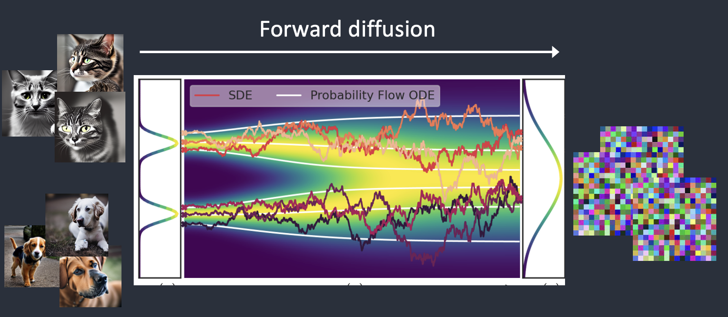
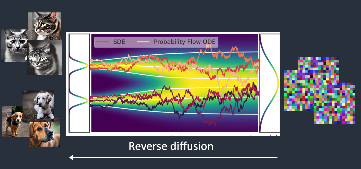
Stable Diffusion is a latent diffusion model that generates AI images from text. Instead of operating in the high-dimensional image space, it first compresses the image into the latent space.
Stable Diffusion belongs to a class of deep learning models called diffusion models. They are generative models, meaning they are designed to generate new data similar to what they have seen in training. In the case of Stable Diffusion, the data are images.
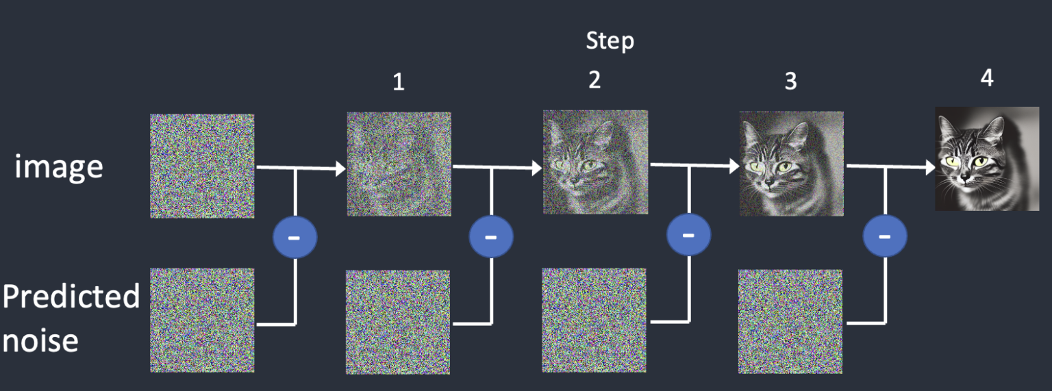
Why is it called the diffusion model? Because its math looks very much like diffusion in physics. Let’s go through the idea.
To reverse the diffusion, we need to know how much noise is added to an image. The answer is teaching a neural network model to predict the noise added. It is called the noise predictor in Stable Diffusion. It is a U-Net model.
After training, we have a noise predictor capable of estimating the noise added to an image.
Diffusion models like Google’s Imagen and Open AI’s DALL-E are in pixel space. They have used some tricks to make the model faster but still not enough.
Stable Diffusion is designed to solve the speed problem. Here’s how.
Stable Diffusion is a latent diffusion model. Instead of operating in the high-dimensional image space, it first compresses the image into the latent space. The latent space is 48 times smaller so it reaps the benefit of crunching a lot fewer numbers.
It is done using a technique called the variational autoencoder. Yes, that’s precisely what the VAE files are, but I will make it crystal clear later.
The Variational Autoencoder (VAE) neural network has two parts: (1) an encoder and (2) a decoder. The encoder compresses an image to a lower dimensional representation in the latent space. The decoder restores the image from the latent space.
You may wonder why the VAE can compress an image into a much smaller latent space without losing information. The reason is, unsurprisingly, natural images are not random. They have high regularity: A face follows a specific spatial relationship between the eyes, nose, cheek, and mouth. A dog has 4 legs and is a particular shape.
In other words, the high dimensionality of images is artifactual. Natural images can be readily compressed into the much smaller latent space without losing any information. This is called the manifold hypothesis in machine learning.
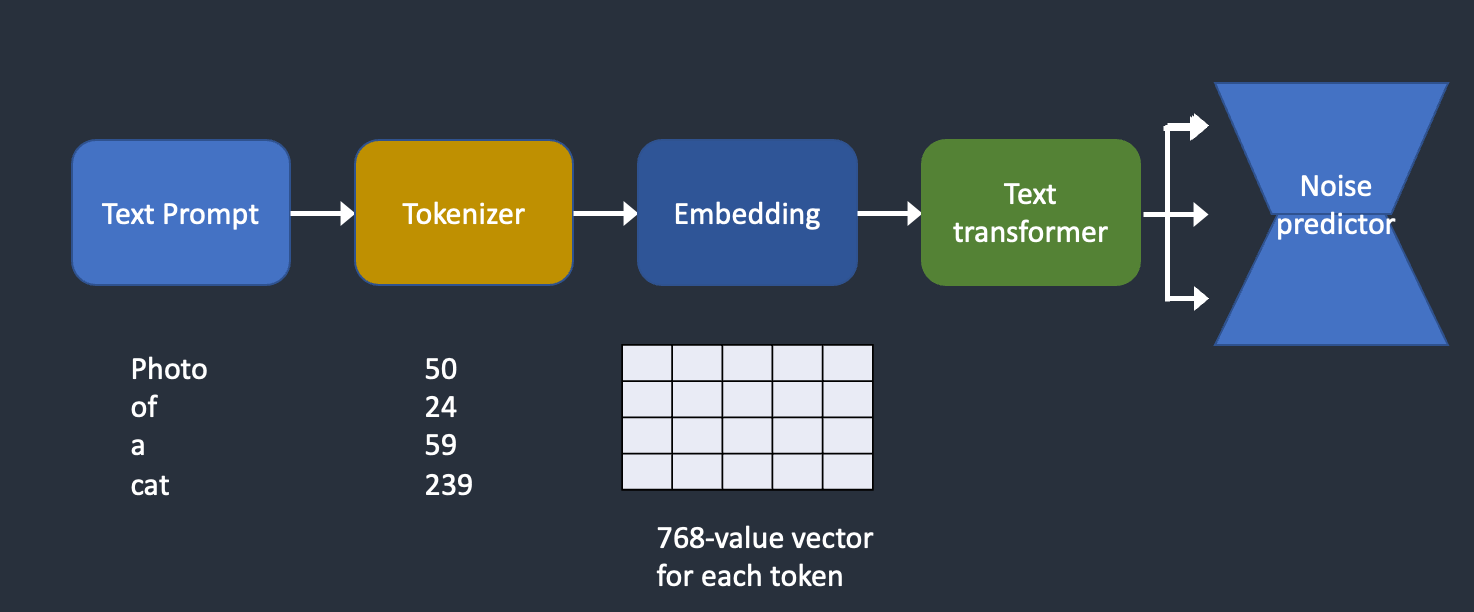
Where does the text prompt enter the picture?
This is where conditioning comes in. The purpose of conditioning is to steer the noise predictor so that the predicted noise will give us what we want after subtracting from the image.
The text prompt is not the only way a Stable Diffusion model can be conditioned. ControlNet conditions the noise predictor with detected outlines, human poses, etc, and achieves excellent controls over image generations.
This write-up won’t be complete without explaining Classifier-Free Guidance (CFG), a value AI artists tinker with every day. To understand what it is, we will need to first touch on its predecessor, classifier guidance…
The classifier guidance scale is a parameter for controlling how closely should the diffusion process follow the label.
Classifier-free guidance, in its authors’ terms, is a way to achieve “classifier guidance without a classifier”. They put the classifier part as conditioning of the noise predictor U-Net, achieving the so-called “classifier-free” (i.e., without a separate image classifier) guidance in image generation.
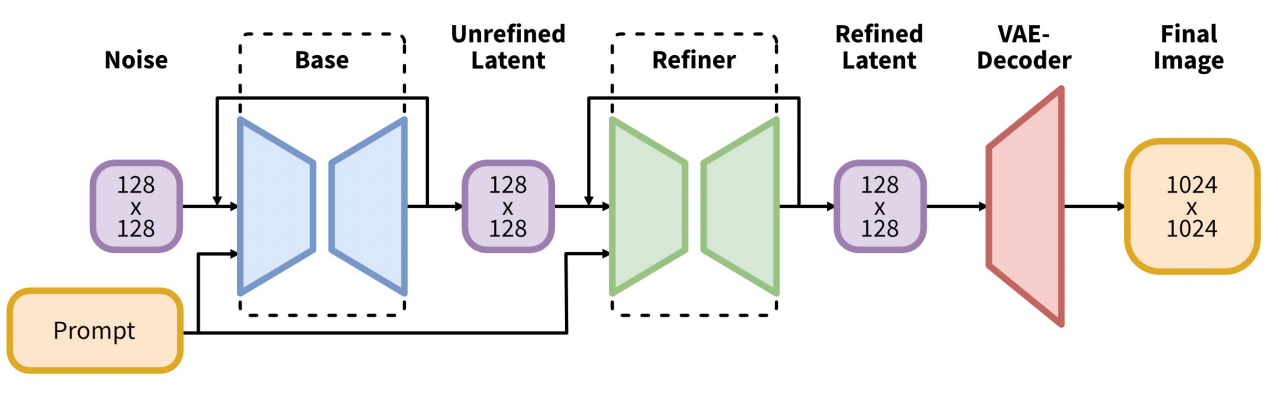
The SDXL model is the official upgrade to the v1 and v2 models. The model is released as open-source software. The total number of parameters of the SDXL model is 6.6 billion, compared with 0.98 billion for the v1.5 model.
The SDXL model is, in practice, two models. You run the base model, followed by the refiner model. The base model sets the global composition. The refiner model adds finer details.
You’re being tricked into believing that AI can produce Hollywood-level videos…
We’re far from it.
Yes, we’ve made huge progress.
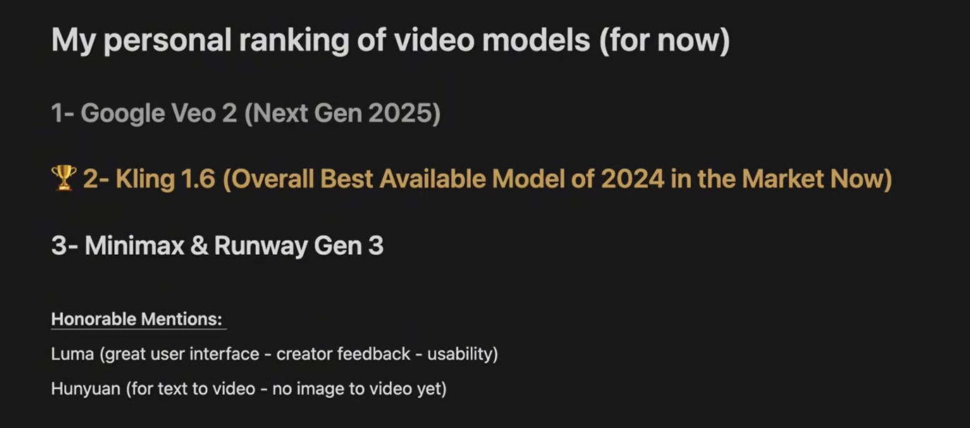
A video sample like this, created using Kling 1.6, is light-years ahead of what was possible a year ago. But there’s still a significant limitation: visual continuity beyond 5 seconds.
Right now, no AI model can maintain consistency beyond a few seconds. That’s why most AI-generated concepts you’re seeing on your feed rely on 2–5 second cuts – it’s all the tech can handle before things start to fall apart.
This isn’t necessarily a problem for creating movie trailers or spec ads. Trailers, for instance, are designed for quick, attention-grabbing rapid cuts, and AI excels at this style of visual storytelling.
But, making a popular, full-length movie with nothing but 5-second shots? That’s absurd.
There are very few exceptions to this rule in modern cinema (e.g., the Bourne franchise).
To bridge the gap between trailers and full-length cinema, AI creative needs to reach 2 key milestones: – 5-12 sec average: ASL for slower, non-action scenes in contemporary films – think conversations, emotional moments, or establishing shots – 30+ sec sequences: Longer, uninterrupted takes are essential for genres that require immersion – drama, romance, thrillers, or any scene that builds tension or atmosphere
Mastering longer cuts is crucial.
30-second continuous shots require a higher level of craftsmanship and visual consistency – you need that 20-30 seconds of breathing room to piece together a variety of scenes and create a compelling movie.
So, where does AI creative stand now?
AI is already transforming industries like auto, fashion, and CPG. These brands can use AI today because short, 2–5 second cuts work perfectly in their visual language. Consumers are accustomed to it, and it simply works. This psychological dynamic is unlikely to change anytime soon.
But for AI to produce true cinema (not just flashy concepts) it needs to extend its visual consistency. And every GenAI company is racing to get there.
The timeline?
Next year, expect breakthroughs in AI-generated content holding consistency for 10+ seconds. By then, full-length commercials, shows, and movies (in that order) will start to feel more crafted, immersive, and intentional, not just stitched together.
If you’re following AI’s impact on creativity, this is the development to watch. The companies that solve continuity will redefine what’s possible in film.
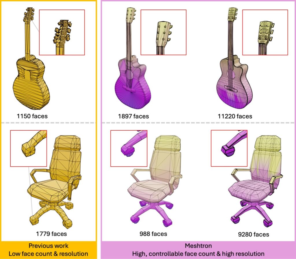
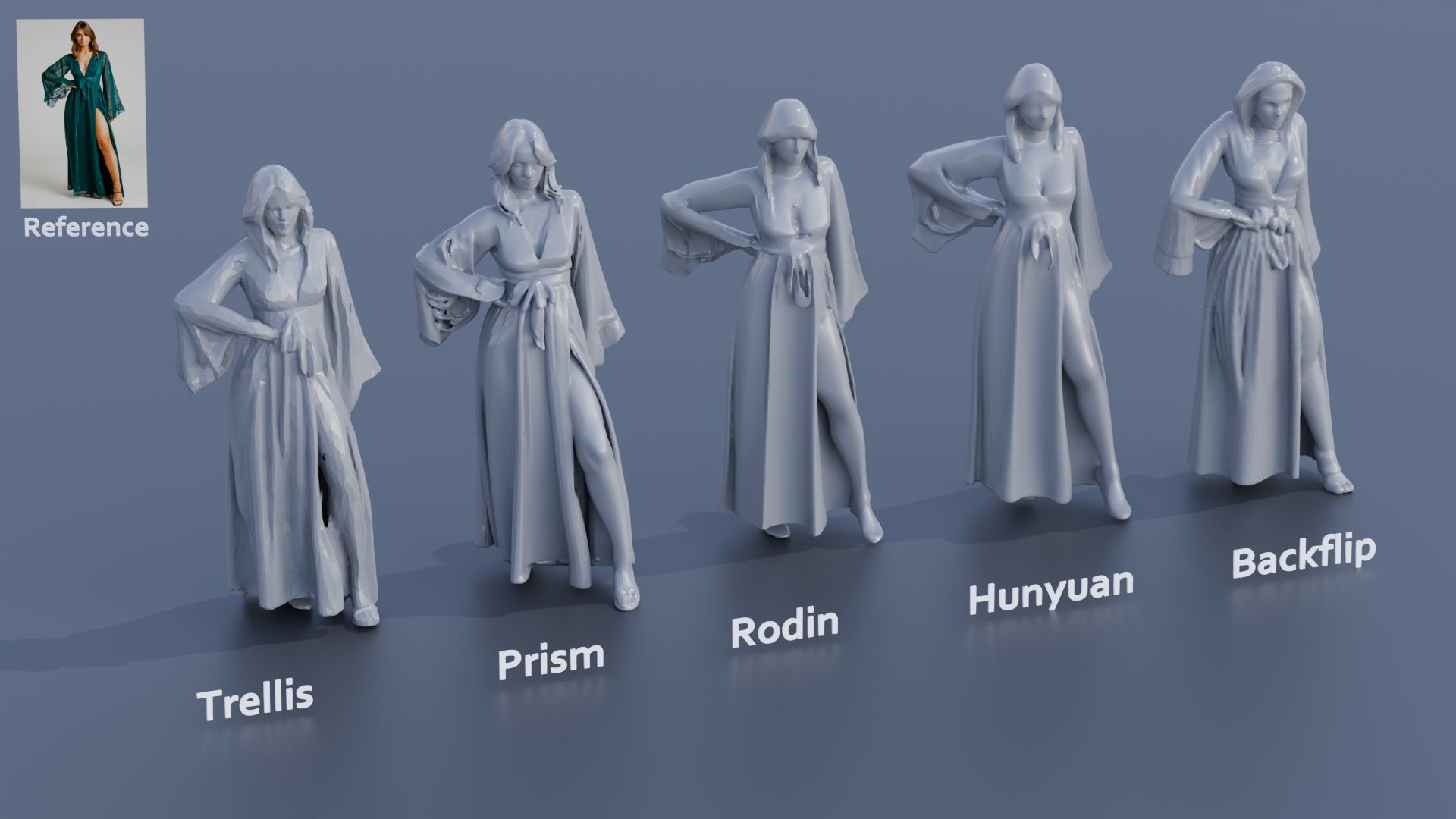
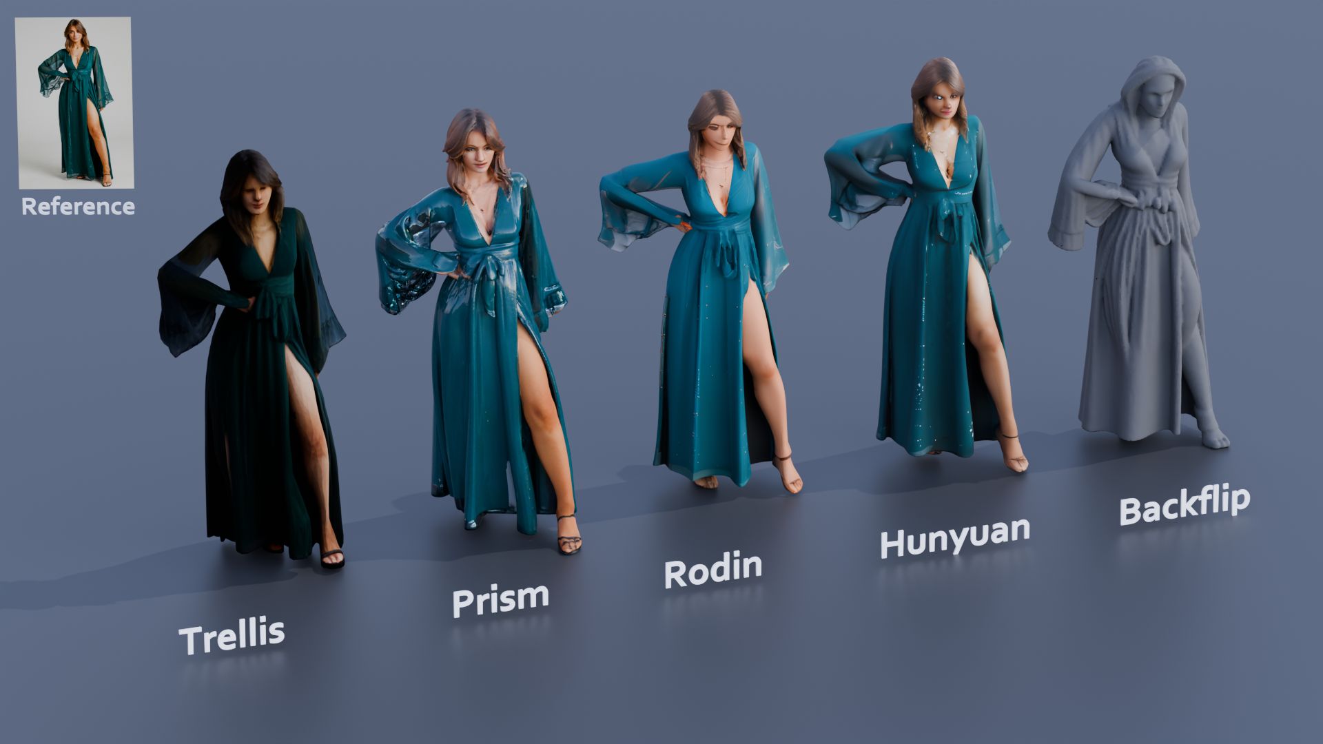
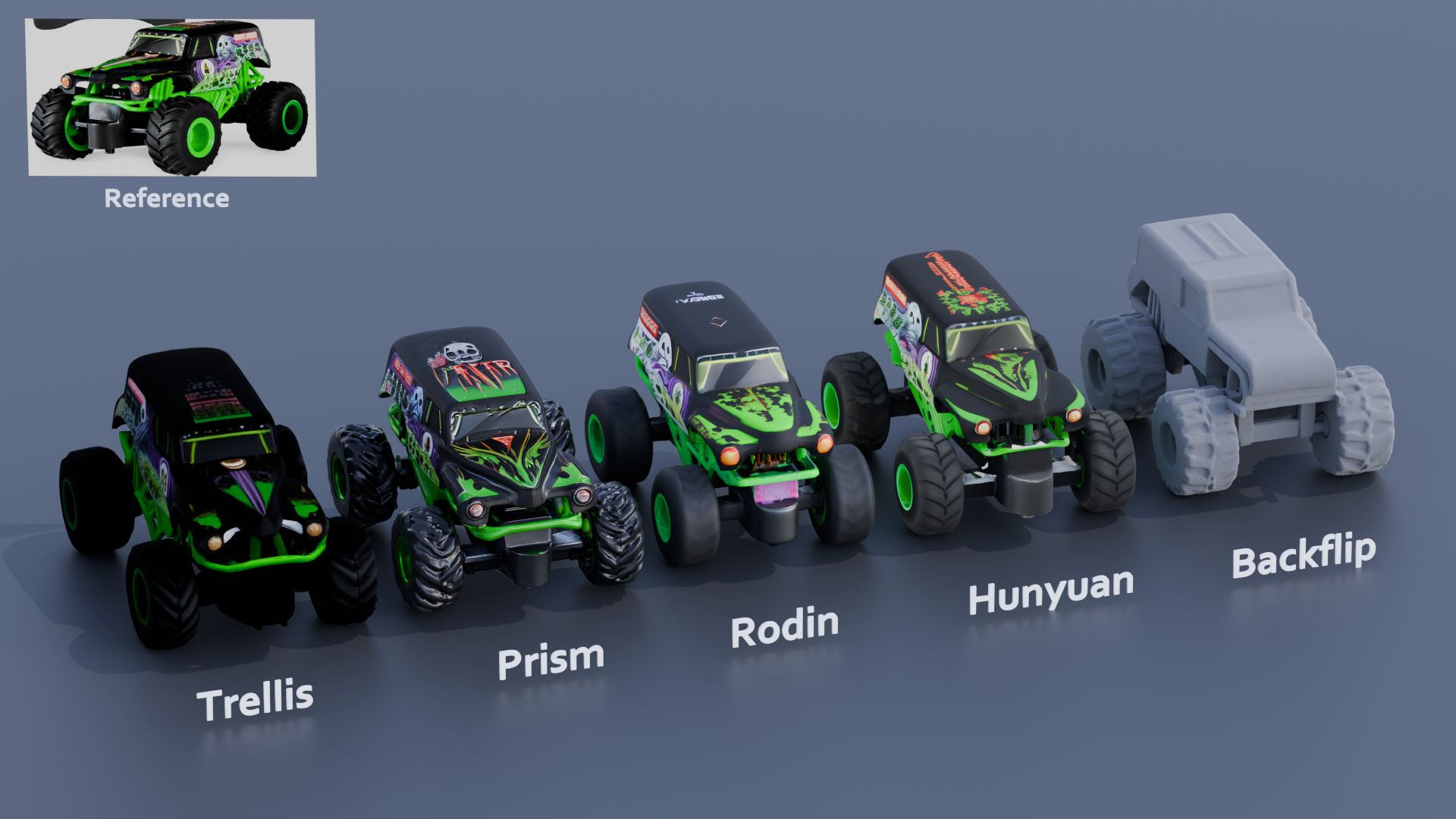
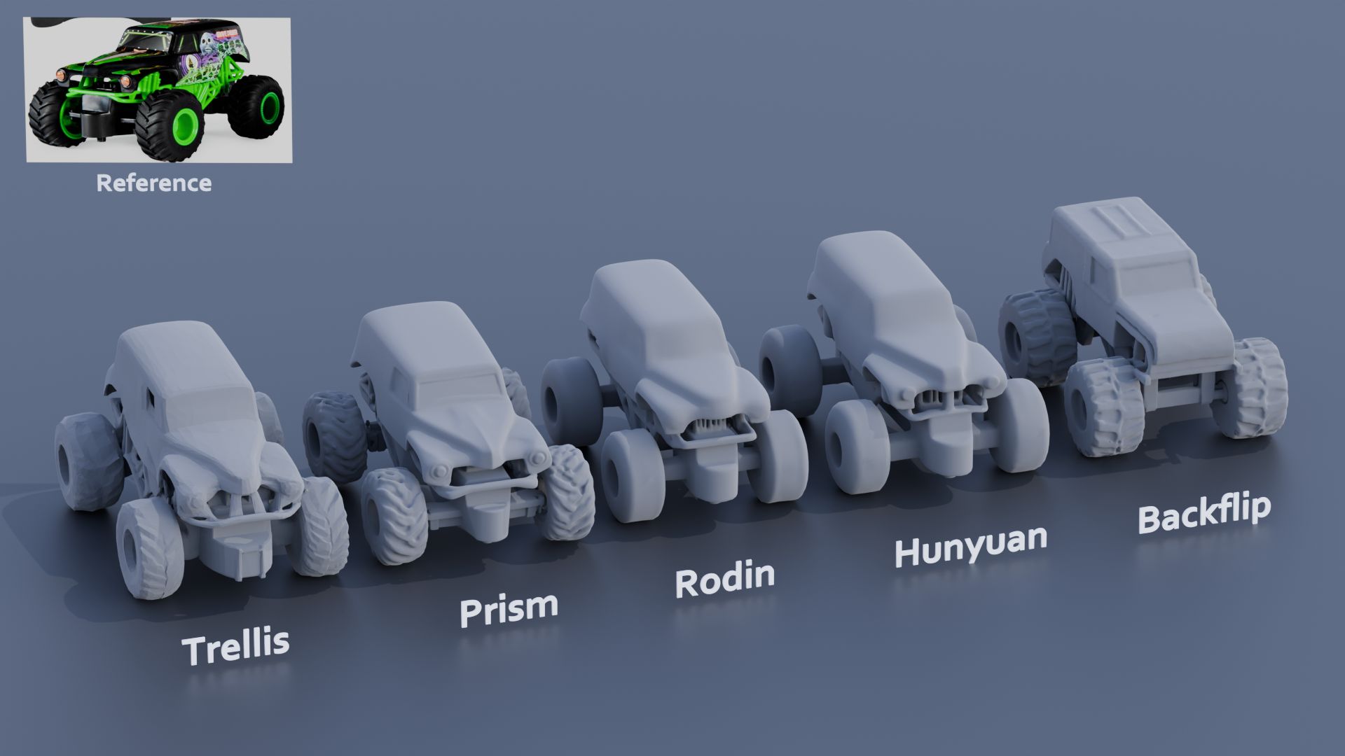
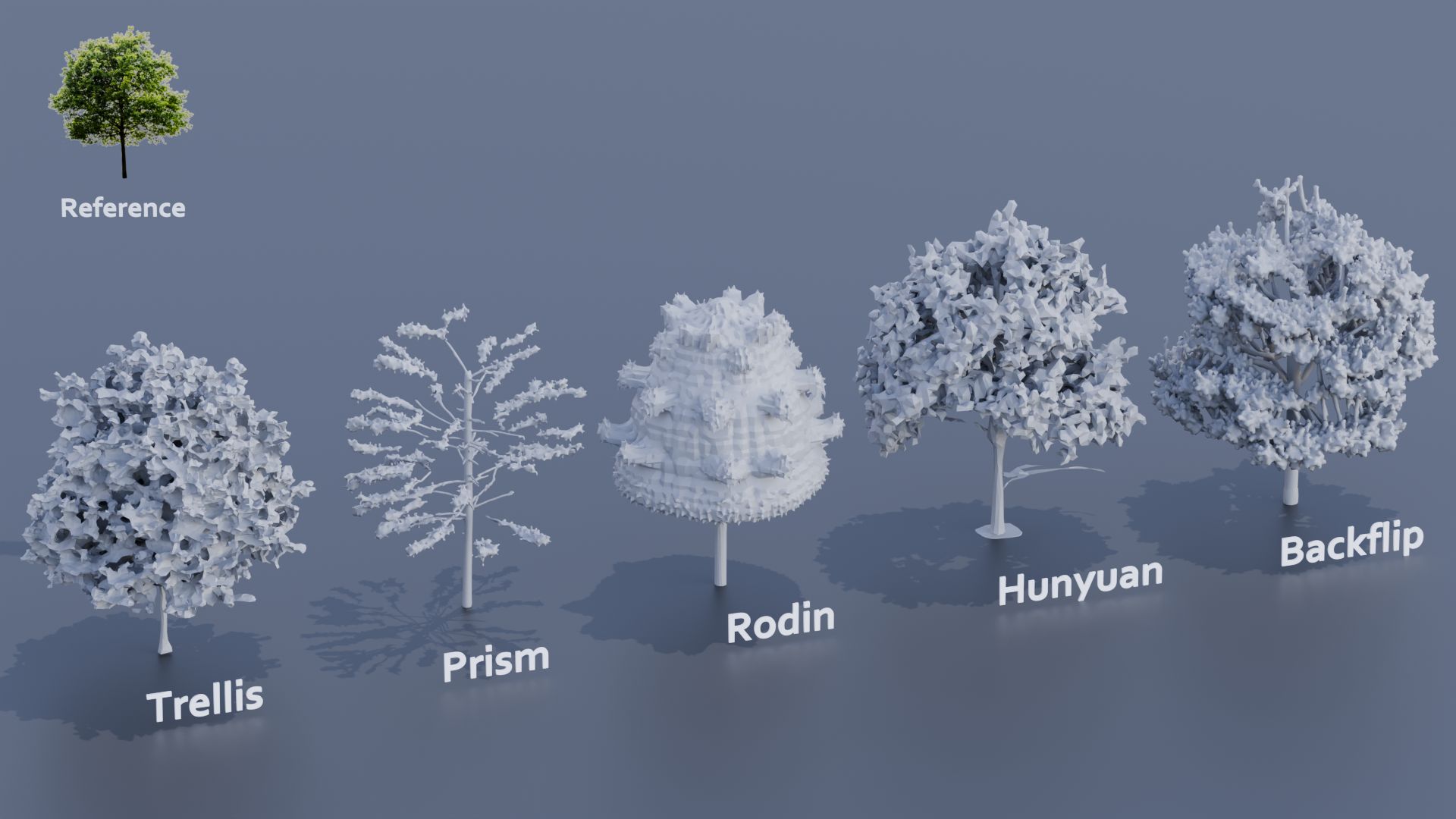
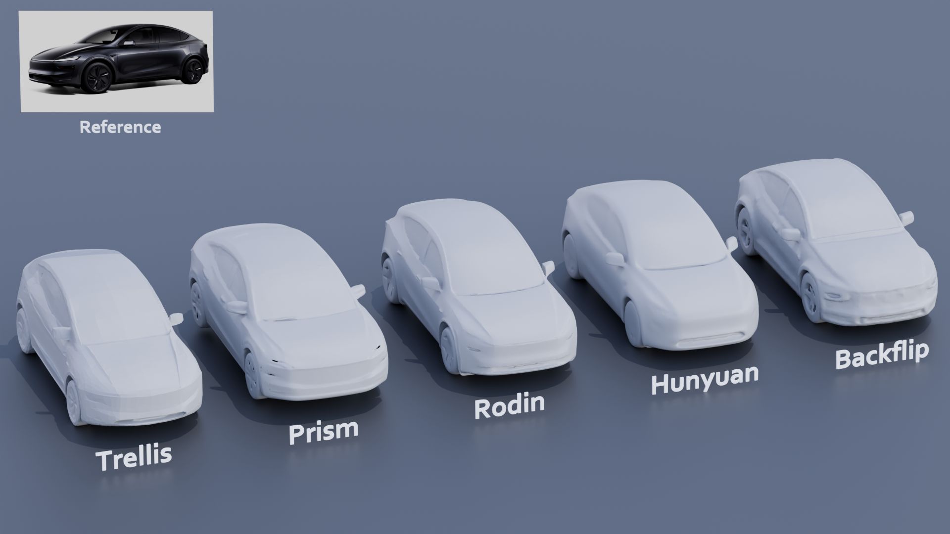
Meshtron provides a simple and scalable, data-driven solution for generating intricate, artist-like meshes of up to 64K faces at 1024-level coordinate resolution. This is over an order of magnitude higher face count and 8x higher coordinate resolution compared to existing methods.
In software development, “technical debt” is a term used to describe the accumulation of shortcuts, suboptimal solutions, and outdated code that occur as developers rush to meet deadlines or prioritize immediate goals over long-term maintainability. While this concept initially seems abstract, its consequences are concrete and can significantly affect the security, usability, and stability of software systems.
The Nature of Technical Debt
Technical debt arises when software engineers choose a less-than-ideal implementation in the interest of saving time or reducing upfront effort. Much like financial debt, these decisions come with an interest rate: over time, the cost of maintaining and updating the system increases, and more effort is required to fix problems that stem from earlier choices. In extreme cases, technical debt can slow development to a crawl, causing future updates or improvements to become far more difficult than they would have been with cleaner, more scalable code.
Impact on Security
One of the most significant threats posed by technical debt is the vulnerability it creates in terms of software security. Outdated code often lacks the latest security patches or is built on legacy systems that are no longer supported. Attackers can exploit these weaknesses, leading to data breaches, ransomware, or other forms of cybercrime. Furthermore, as systems grow more complex and the debt compounds, identifying and fixing vulnerabilities becomes increasingly challenging. Failing to address technical debt leaves an organization exposed to security risks that may only become apparent after a costly incident.
Impact on Usability
Technical debt also affects the user experience. Systems burdened by outdated code often become clunky and slow, leading to poor usability. Engineers may find themselves continuously patching minor issues rather than implementing larger, user-centric improvements. Over time, this results in a product that feels antiquated, is difficult to use, or lacks modern functionality. In a competitive market, poor usability can alienate users, causing a loss of confidence and driving them to alternative products or services.
Impact on Stability
Stability is another critical area impacted by technical debt. As developers add features or make updates to systems weighed down by previous quick fixes, they run the risk of introducing bugs or causing system crashes. The tangled, fragile nature of code laden with technical debt makes troubleshooting difficult and increases the likelihood of cascading failures. Over time, instability in the software can erode both the trust of users and the efficiency of the development team, as more resources are dedicated to resolving recurring issues rather than innovating or expanding the system’s capabilities.
The Long-Term Costs of Ignoring Technical Debt
While technical debt can provide short-term gains by speeding up initial development, the long-term costs are much higher. Unaddressed technical debt can lead to project delays, escalating maintenance costs, and an ever-widening gap between current code and modern best practices. The more technical debt accumulates, the harder and more expensive it becomes to address. For many companies, failing to pay down this debt eventually results in a critical juncture: either invest heavily in refactoring the codebase or face an expensive overhaul to rebuild from the ground up.
Conclusion
Technical debt is an unavoidable aspect of software development, but understanding its perils is essential for minimizing its impact on security, usability, and stability. By actively managing technical debt—whether through regular refactoring, code audits, or simply prioritizing long-term quality over short-term expedience—organizations can avoid the most dangerous consequences and ensure their software remains robust and reliable in an ever-changing technological landscape.
For years, tech firms were fighting a war for talent. Now they are waging war on talent.
This shift has led to a weakening of the social contract between employees and employers, with culture and employee values being sidelined in favor of financial discipline and free cash flow.
The operating environment has changed from a high tolerance for failure (where cheap capital and willing spenders accepted slipped dates and feature lag) to a very low – if not zero – tolerance for failure (fiscal discipline is in vogue again).
While preventing and containing mistakes staves off shocks to the income statement, it doesn’t fundamentally reduce costs. Years of payroll bloat – aggressive hiring, aggressive comp packages to attract and retain people – make labor the biggest cost in tech. …
Of course, companies can reduce their labor force through natural attrition. Other labor policy changes – return to office mandates, contraction of fringe benefits, reduction of job promotions, suspension of bonuses and comp freezes – encourage more people to exit voluntarily. It’s cheaper to let somebody self-select out than it is to lay them off. …
Employees recruited in more recent years from outside the ranks of tech were given the expectation that we’ll teach you what you need to know, we want you to join because we value what you bring to the table. That is no longer applicable. Runway for individual growth is very short in zero-tolerance-for-failure operating conditions. Job preservation, at least in the short term for this cohort, comes from completing corporate training and acquiring professional certifications. Training through community or experience is not in the cards. …
The ability to perform competently in multiple roles, the extra-curriculars, the self-directed enrichment, the ex-company leadership – all these things make no matter. The calculus is what you got paid versus how you performed on objective criteria relative to your cohort. Nothing more. …
Here is where the change in the social contract is perhaps the most blatant. In the “destination employer” years, the employee invested in the community and its values, and the employer rewarded the loyalty of its employees through things like runway for growth (stretch roles and sponsored work innovation) and tolerance for error (valuing demonstrable learning over perfection in execution). No longer. …
Open-source fonts packaged into individual NPM packages for self-hosting in web applications. Self-hosting fonts can significantly improve website performance, remain version-locked, work offline, and offer more privacy.
Building a successful business requires a focus on three key elements: product excellence, go-to-market strategy, and operational excellence. Neglecting any of these areas can lead to failure, as evidenced by the high percentage of startups that don’t make it past the five-year mark. Founders and CEOs must ensure a solid product foundation while also integrating effective sales, marketing, and management strategies to achieve sustainable growth and scale.
Foundation: Product Excellence, Core Values and Mission
Core Values: These are the guiding principles that dictate behavior and action within the company. They form the ethical foundation and are crucial for maintaining consistency in decision-making.
Mission: This defines the company’s purpose and goals. A clear and compelling mission helps align the team and provides a sense of direction.
Efficiency and Scalability: This layer focuses on creating efficient processes that can scale as the company grows. Streamlined operations reduce costs and increase productivity.
Structure: Operational Excellence and Innovation
Operational Excellence: Efficient processes, quality control, and continuous improvement fall into this layer. Ensuring that the company operates smoothly and effectively is crucial for sustainability.
Innovation: Staying competitive requires innovation. This involves developing new products, services, or processes that add value and keep the company relevant in the market.
Quality Control and Continuous Improvement: Ensuring that operational processes are of high quality and constantly improving helps maintain product excellence and customer satisfaction.
Technology and Infrastructure: Investing in the right technology and infrastructure to support business operations is vital. This includes everything from manufacturing equipment to software systems that enhance operational efficiency.
Strategy: Go-to-Market Strategy, Vision and Long-Term Planning
Vision: A forward-looking vision inspires and motivates the team. It outlines where the company aims to be in the future and helps in setting long-term goals.
Strategic Planning: This involves setting long-term goals and determining the actions and resources needed to achieve them. It includes market analysis, competitive strategy, and growth planning.
Market Understanding: A deep understanding of the target market, including customer segments, competitors, and market trends, is essential. This knowledge helps in positioning the product effectively.
Marketing and Sales Execution: This involves creating a robust marketing plan that includes branding, messaging, and advertising strategies to attract and retain customers. Additionally, building a strong sales strategy ensures that the product reaches the right customers through the right channels.
Customer Acquisition and Retention: Effective strategies for acquiring new customers and retaining existing ones are critical. This includes loyalty programs, customer service excellence, and engagement initiatives.
3. Generative AI Fundamentals: Earn a skill badge by demonstrating your understanding of foundational concepts in Generative AI. https://www.cloudskillsboost.google/paths
7. Transformer Models and BERT Model: Get a comprehensive introduction to the Transformer architecture and the Bidirectional Encoder Representations from the Transformers (BERT) model. https://www.cloudskillsboost.google/course_templates/538
The human eye perceives half scene brightness not as the linear 50% of the present energy (linear nature values) but as 18% of the overall brightness. We are biased to perceive more information in the dark and contrast areas. A Macbeth chart helps with calibrating back into a photographic capture into this “human perspective” of the world.
In photography, painting, and other visual arts, middle gray or middle grey is a tone that is perceptually about halfway between black and white on a lightness scale in photography and printing, it is typically defined as 18% reflectance in visible light
Light meters, cameras, and pictures are often calibrated using an 18% gray card[4][5][6] or a color reference card such as a ColorChecker. On the assumption that 18% is similar to the average reflectance of a scene, a grey card can be used to estimate the required exposure of the film.
The exposure meter in the camera does not know whether the subject itself is bright or not. It simply measures the amount of light that comes in, and makes a guess based on that. The camera will aim for 18% gray independently, meaning if you take a photo of an entirely white surface, and an entirely black surface you should get two identical images which both are gray (at least in theory). Thus enters the Macbeth chart.
<!–more–>
Note that Chroma Key Green is reasonably close to an 18% gray reflectance.
In color technology, color depth also known as bit depth, is either the number of bits used to indicate the color of a single pixel, OR the number of bits used for each color component of a single pixel.
When referring to a pixel, the concept can be defined as bits per pixel (bpp).
When referring to a color component, the concept can be defined as bits per component, bits per channel, bits per color (all three abbreviated bpc), and also bits per pixel component, bits per color channel or bits per sample (bps). Modern standards tend to use bits per component, but historical lower-depth systems used bits per pixel more often.
Color depth is only one aspect of color representation, expressing the precision with which the amount of each primary can be expressed; the other aspect is how broad a range of colors can be expressed (the gamut). The definition of both color precision and gamut is accomplished with a color encoding specification which assigns a digital code value to a location in a color space.
Here’s a simple explanation of each.
8-bit images (i.e. 24 bits per pixel for a color image) are considered Low Dynamic Range. They can store around 5 stops of light and each pixel carry a value from 0 (black) to 255 (white). As a comparison, DSLR cameras can capture ~12-15 stops of light and they use RAW files to store the information.
16-bit: This format is commonly referred to as “half-precision.” It uses 16 bits of data to represent color values for each pixel. With 16 bits, you can have 65,536 discrete levels of color, allowing for relatively high precision and smooth gradients. However, it has a limited dynamic range, meaning it cannot accurately represent extremely bright or dark values. It is commonly used for regular images and textures.
16-bit float: This format is an extension of the 16-bit format but uses floating-point numbers instead of fixed integers. Floating-point numbers allow for more precise calculations and a larger dynamic range. In this case, the 16 bits are used to store both the color value and the exponent, which controls the range of values that can be represented. The 16-bit float format provides better accuracy and a wider dynamic range than regular 16-bit, making it useful for high-dynamic-range imaging (HDRI) and computations that require more precision.
32-bit: (i.e. 96 bits per pixel for a color image) are considered High Dynamic Range. This format, also known as “full-precision” or “float,” uses 32 bits to represent color values and offers the highest precision and dynamic range among the three options. With 32 bits, you have a significantly larger number of discrete levels, allowing for extremely accurate color representation, smooth gradients, and a wide range of brightness values. It is commonly used for professional rendering, visual effects, and scientific applications where maximum precision is required.
Bits and HDR coverage
High Dynamic Range (HDR) images are designed to capture a wide range of luminance values, from the darkest shadows to the brightest highlights, in order to reproduce a scene with more accuracy and detail. The bit depth of an image refers to the number of bits used to represent each pixel’s color information. When comparing 32-bit float and 16-bit float HDR images, the drop in accuracy primarily relates to the precision of the color information.
A 32-bit float HDR image offers a higher level of precision compared to a 16-bit float HDR image. In a 32-bit float format, each color channel (red, green, and blue) is represented by 32 bits, allowing for a larger range of values to be stored. This increased precision enables the image to retain more details and subtleties in color and luminance.
On the other hand, a 16-bit float HDR image utilizes 16 bits per color channel, resulting in a reduced range of values that can be represented. This lower precision leads to a loss of fine details and color nuances, especially in highly contrasted areas of the image where there are significant differences in luminance.
The drop in accuracy between 32-bit and 16-bit float HDR images becomes more noticeable as the exposure range of the scene increases. Exposure range refers to the span between the darkest and brightest areas of an image. In scenes with a limited exposure range, where the luminance differences are relatively small, the loss of accuracy may not be as prominent or perceptible. These images usually are around 8-10 exposure levels.
However, in scenes with a wide exposure range, such as a landscape with deep shadows and bright highlights, the reduced precision of a 16-bit float HDR image can result in visible artifacts like color banding, posterization, and loss of detail in both shadows and highlights. The image may exhibit abrupt transitions between tones or colors, which can appear unnatural and less realistic.
To provide a rough estimate, it is often observed that exposure values beyond approximately ±6 to ±8 stops from the middle gray (18% reflectance) may be more prone to accuracy issues in a 16-bit float format. This range may vary depending on the specific implementation and encoding scheme used.
To summarize, the drop in accuracy between 32-bit and 16-bit float HDR images is mainly related to the reduced precision of color information. This decrease in precision becomes more apparent in scenes with a wide exposure range, affecting the representation of fine details and leading to visible artifacts in the image.
In practice, this means that exposure values beyond a certain range will experience a loss of accuracy and detail when stored in a 16-bit float format. The exact range at which this loss occurs depends on the encoding scheme and the specific implementation. However, in general, extremely bright or extremely dark values that fall outside the representable range may be subject to quantization errors, resulting in loss of detail, banding, or other artifacts.
HDRs used for lighting purposes are usually slightly convolved to improve on sampling speed and removing specular artefacts. To that extent, 16 bit float HDRIs tend to me most used in CG cycles.
2- tune the caption with ChatGPT as suggested by Pixaroma: Craft detailed prompts for Al (image/video) generation, avoiding quotation marks. When I provide a description or image, translate it into a prompt that captures a cinematic, movie-like quality, focusing on elements like scene, style, mood, lighting, and specific visual details. Ensure that the prompt evokes a rich, immersive atmosphere, emphasizing textures, depth, and realism. Always incorporate (static/slow) camera or cinematic movement to enhance the feeling of fluidity and visual storytelling. Keep the wording precise yet descriptive, directly usable, and designed to achieve a high-quality, film-inspired result.
1. Use the 80/20 principle to learn faster Prompt: “I want to learn about [insert topic]. Identify and share the most important 20% of learnings from this topic that will help me understand 80% of it.”
2. Learn and develop any new skill Prompt: “I want to learn/get better at [insert desired skill]. I am a complete beginner. Create a 30-day learning plan that will help a beginner like me learn and improve this skill.”
3. Summarize long documents and articles Prompt: “Summarize the text below and give me a list of bullet points with key insights and the most important facts.” [Insert text]
4. Train ChatGPT to generate prompts for you Prompt: “You are an AI designed to help [insert profession]. Generate a list of the 10 best prompts for yourself. The prompts should be about [insert topic].”
5. Master any new skill Prompt: “I have 3 free days a week and 2 months. Design a crash study plan to master [insert desired skill].”
6. Simplify complex information Prompt: “Break down [insert topic] into smaller, easier-to-understand parts. Use analogies and real-life examples to simplify the concept and make it more relatable.”
Display Referred it is tied to the target hardware, as such it bakes color requirements into every type of media output request.
Scene Referred uses a common unified wide gamut and targeting audience through CDL and DI libraries instead.
So that color information stays untouched and only “transformed” as/when needed.
Sources:
– Victor Perez – Color Management Fundamentals & ACES Workflows in Nuke
– https://z-fx.nl/ColorspACES.pdf – Wicus
“Simon Willison created a Datasette browser to explore WebVid-10M, one of the two datasets used to train the video generation model, and quickly learned that all 10.7 million video clips were scraped from Shutterstock, watermarks and all.”
“In addition to the Shutterstock clips, Meta also used 10 million video clips from this 100M video dataset from Microsoft Research Asia. It’s not mentioned on their GitHub, but if you dig into the paper, you learn that every clip came from over 3 million YouTube videos.”
“It’s become standard practice for technology companies working with AI to commercially use datasets and models collected and trained by non-commercial research entities like universities or non-profits.”
“Like with the artists, photographers, and other creators found in the 2.3 billion images that trained Stable Diffusion, I can’t help but wonder how the creators of those 3 million YouTube videos feel about Meta using their work to train their new model.”
DISCLAIMER – Links and images on this website may be protected by the respective owners’ copyright. All data submitted by users through this site shall be treated as freely available to share.


