Views :
1,316


3Dprinting (172) A.I. (665) animation (335) blender (194) colour (225) commercials (46) composition (150) cool (358) design (627) Featured (65) hardware (302) IOS (109) jokes (134) lighting (278) modeling (116) music (183) photogrammetry (171) photography (744) production (1233) python (84) quotes (485) reference (305) software (1319) trailers (295) ves (522) VR (219)
RASTERIZATION
Rasterisation (or rasterization) is the task of taking the information described in a vector graphics format OR the vertices of triangles making 3D shapes and converting them into a raster image (a series of pixels, dots or lines, which, when displayed together, create the image which was represented via shapes), or in other words “rasterizing” vectors or 3D models onto a 2D plane for display on a computer screen.
For each triangle of a 3D shape, you project the corners of the triangle on the virtual screen with some math (projective geometry). Then you have the position of the 3 corners of the triangle on the pixel screen. Those 3 points have texture coordinates, so you know where in the texture are the 3 corners. The cost is proportional to the number of triangles, and is only a little bit affected by the screen resolution.
In computer graphics, a raster graphics or bitmap image is a dot matrix data structure that represents a generally rectangular grid of pixels (points of color), viewable via a monitor, paper, or other display medium.
With rasterization, objects on the screen are created from a mesh of virtual triangles, or polygons, that create 3D models of objects. A lot of information is associated with each vertex, including its position in space, as well as information about color, texture and its “normal,” which is used to determine the way the surface of an object is facing.
Computers then convert the triangles of the 3D models into pixels, or dots, on a 2D screen. Each pixel can be assigned an initial color value from the data stored in the triangle vertices.
Further pixel processing or “shading,” including changing pixel color based on how lights in the scene hit the pixel, and applying one or more textures to the pixel, combine to generate the final color applied to a pixel.
The main advantage of rasterization is its speed. However, rasterization is simply the process of computing the mapping from scene geometry to pixels and does not prescribe a particular way to compute the color of those pixels. So it cannot take shading, especially the physical light, into account and it cannot promise to get a photorealistic output. That’s a big limitation of rasterization.
There are also multiple problems:
If you have two triangles one is behind the other, you will draw twice all the pixels. you only keep the pixel from the triangle that is closer to you (Z-buffer), but you still do the work twice.
The borders of your triangles are jagged as it is hard to know if a pixel is in the triangle or out. You can do some smoothing on those, that is anti-aliasing.
You have to handle every triangles (including the ones behind you) and then see that they do not touch the screen at all. (we have techniques to mitigate this where we only look at triangles that are in the field of view)
Transparency is hard to handle (you can’t just do an average of the color of overlapping transparent triangles, you have to do it in the right order)


RAY CASTING
It is almost the exact reverse of rasterization: you start from the virtual screen instead of the vector or 3D shapes, and you project a ray, starting from each pixel of the screen, until it intersect with a triangle.
The cost is directly correlated to the number of pixels in the screen and you need a really cheap way of finding the first triangle that intersect a ray. In the end, it is more expensive than rasterization but it will, by design, ignore the triangles that are out of the field of view.
You can use it to continue after the first triangle it hit, to take a little bit of the color of the next one, etc… This is useful to handle the border of the triangle cleanly (less jagged) and to handle transparency correctly.
RAYTRACING


Same idea as ray casting except once you hit a triangle you reflect on it and go into a different direction. The number of reflection you allow is the “depth” of your ray tracing. The color of the pixel can be calculated, based off the light source and all the polygons it had to reflect off of to get to that screen pixel.
The easiest way to think of ray tracing is to look around you, right now. The objects you’re seeing are illuminated by beams of light. Now turn that around and follow the path of those beams backwards from your eye to the objects that light interacts with. That’s ray tracing.
Ray tracing is eye-oriented process that needs walking through each pixel looking for what object should be shown there, which is also can be described as a technique that follows a beam of light (in pixels) from a set point and simulates how it reacts when it encounters objects.
Compared with rasterization, ray tracing is hard to be implemented in real time, since even one ray can be traced and processed without much trouble, but after one ray bounces off an object, it can turn into 10 rays, and those 10 can turn into 100, 1000…The increase is exponential, and the the calculation for all these rays will be time consuming.
Historically, computer hardware hasn’t been fast enough to use these techniques in real time, such as in video games. Moviemakers can take as long as they like to render a single frame, so they do it offline in render farms. Video games have only a fraction of a second. As a result, most real-time graphics rely on the another technique called rasterization.

PATH TRACING
Path tracing can be used to solve more complex lighting situations.
Path tracing is a type of ray tracing. When using path tracing for rendering, the rays only produce a single ray per bounce. The rays do not follow a defined line per bounce (to a light, for example), but rather shoot off in a random direction. The path tracing algorithm then takes a random sampling of all of the rays to create the final image. This results in sampling a variety of different types of lighting.
When a ray hits a surface it doesn’t trace a path to every light source, instead it bounces the ray off the surface and keeps bouncing it until it hits a light source or exhausts some bounce limit.
It then calculates the amount of light transferred all the way to the pixel, including any color information gathered from surfaces along the way.
It then averages out the values calculated from all the paths that were traced into the scene to get the final pixel color value.
It requires a ton of computing power and if you don’t send out enough rays per pixel or don’t trace the paths far enough into the scene then you end up with a very spotty image as many pixels fail to find any light sources from their rays. So when you increase the the samples per pixel, you can see the image quality becomes better and better.
Ray tracing tends to be more efficient than path tracing. Basically, the render time of a ray tracer depends on the number of polygons in the scene. The more polygons you have, the longer it will take.
Meanwhile, the rendering time of a path tracer can be indifferent to the number of polygons, but it is related to light situation: If you add a light, transparency, translucence, or other shader effects, the path tracer will slow down considerably.

blogs.nvidia.com/blog/2018/03/19/whats-difference-between-ray-tracing-rasterization/
https://en.wikipedia.org/wiki/Rasterisation
https://www.quora.com/Whats-the-difference-between-ray-tracing-and-path-tracing


Color Temperature of a light source describes the spectrum of light which is radiated from a theoretical “blackbody” (an ideal physical body that absorbs all radiation and incident light – neither reflecting it nor allowing it to pass through) with a given surface temperature.
https://en.wikipedia.org/wiki/Color_temperature
Or. Most simply it is a method of describing the color characteristics of light through a numerical value that corresponds to the color emitted by a light source, measured in degrees of Kelvin (K) on a scale from 1,000 to 10,000.
More accurately. The color temperature of a light source is the temperature of an ideal backbody that radiates light of comparable hue to that of the light source.
As such, the color temperature of a light source is a numerical measurement of its color appearance. It is based on the principle that any object will emit light if it is heated to a high enough temperature, and that the color of that light will shift in a predictable manner as the temperature is increased. The system is based on the color changes of a theoretical “blackbody radiator” as it is heated from a cold black to a white hot state.
So, why do we measure the hue of the light as a “temperature”? This was started in the late 1800s, when the British physicist William Kelvin heated a block of carbon. It glowed in the heat, producing a range of different colors at different temperatures. The black cube first produced a dim red light, increasing to a brighter yellow as the temperature went up, and eventually produced a bright blue-white glow at the highest temperatures. In his honor, Color Temperatures are measured in degrees Kelvin, which are a variation on Centigrade degrees. Instead of starting at the temperature water freezes, the Kelvin scale starts at “absolute zero,” which is -273 Centigrade.
More about black bodies here: https://www.pixelsham.com/2013/03/14/black-body-color

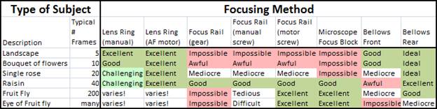
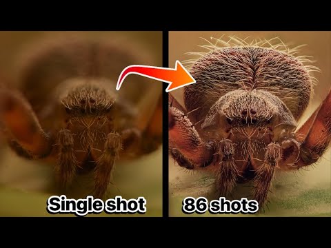
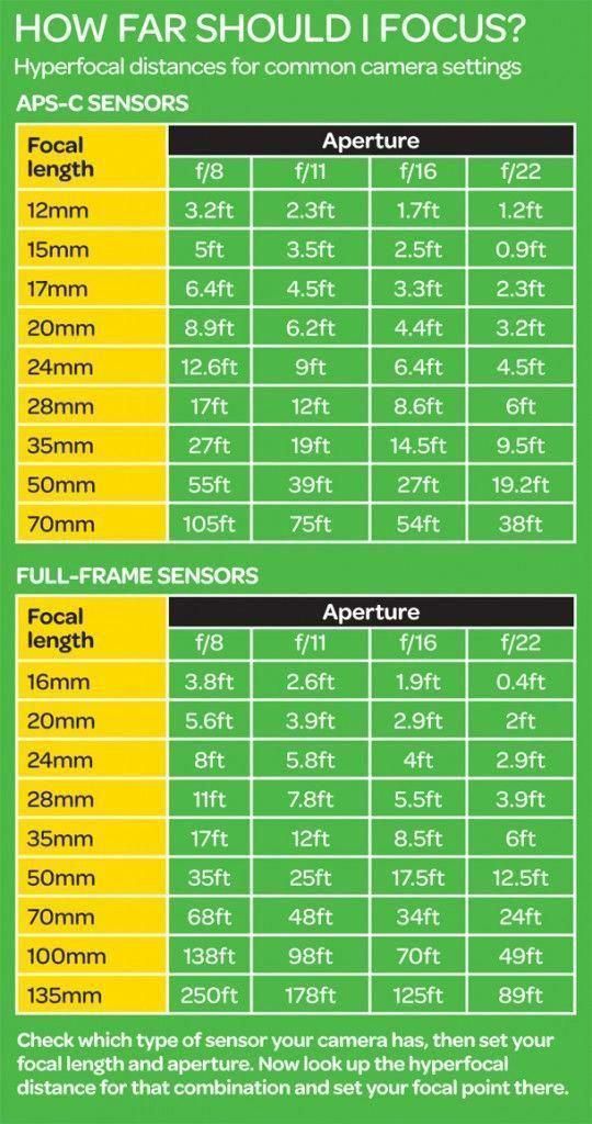
Details in the post

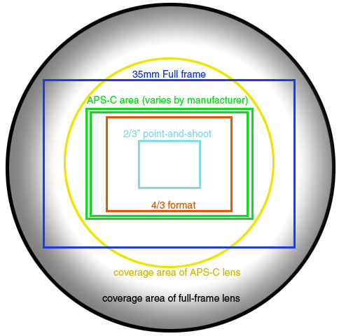
The main question being: Is it better to use a macro rail or is it better to vary the focus of the lens?
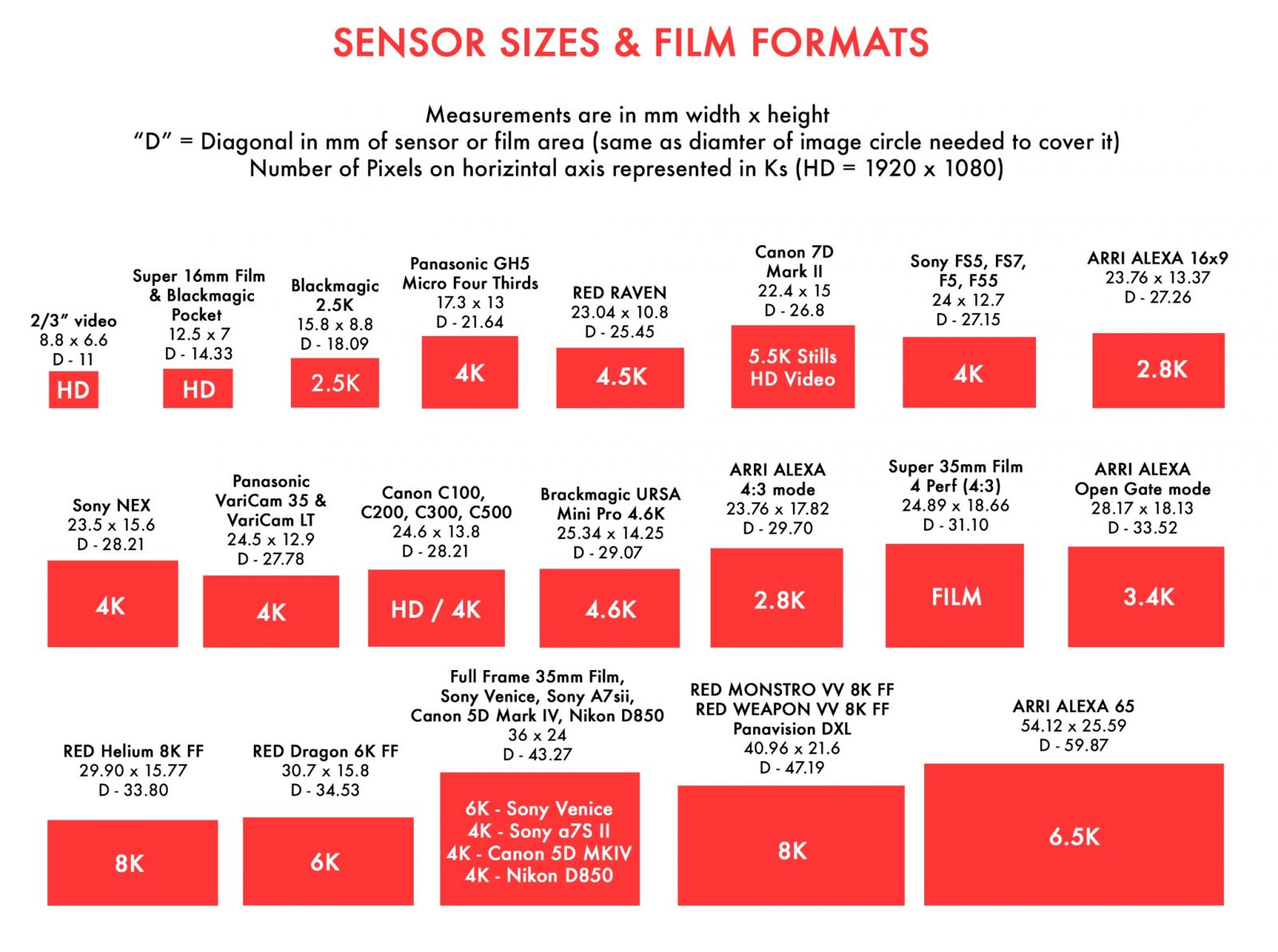
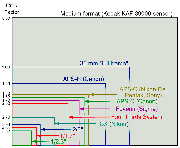
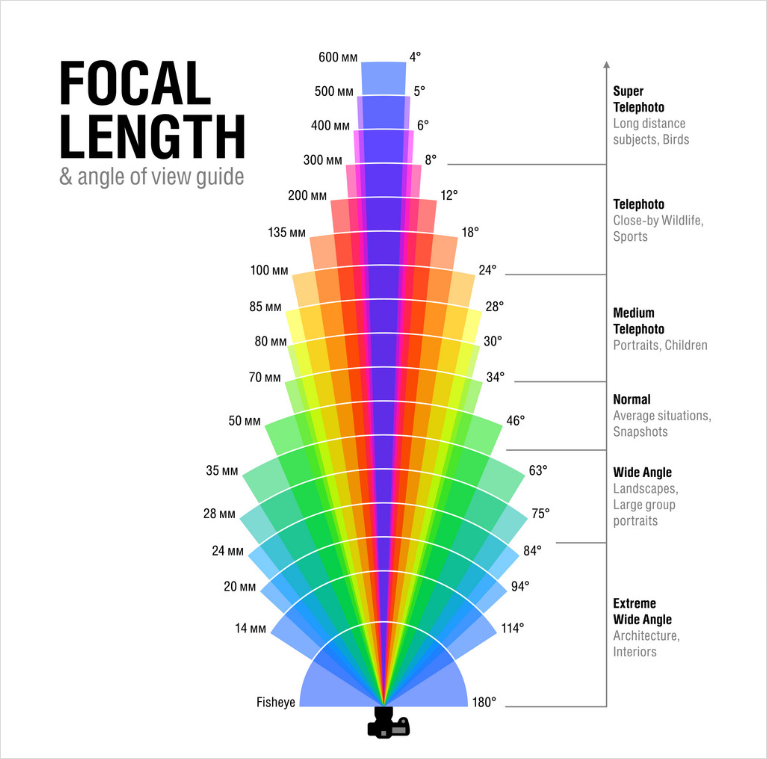
https://en.wikipedia.org/wiki/Focal_length
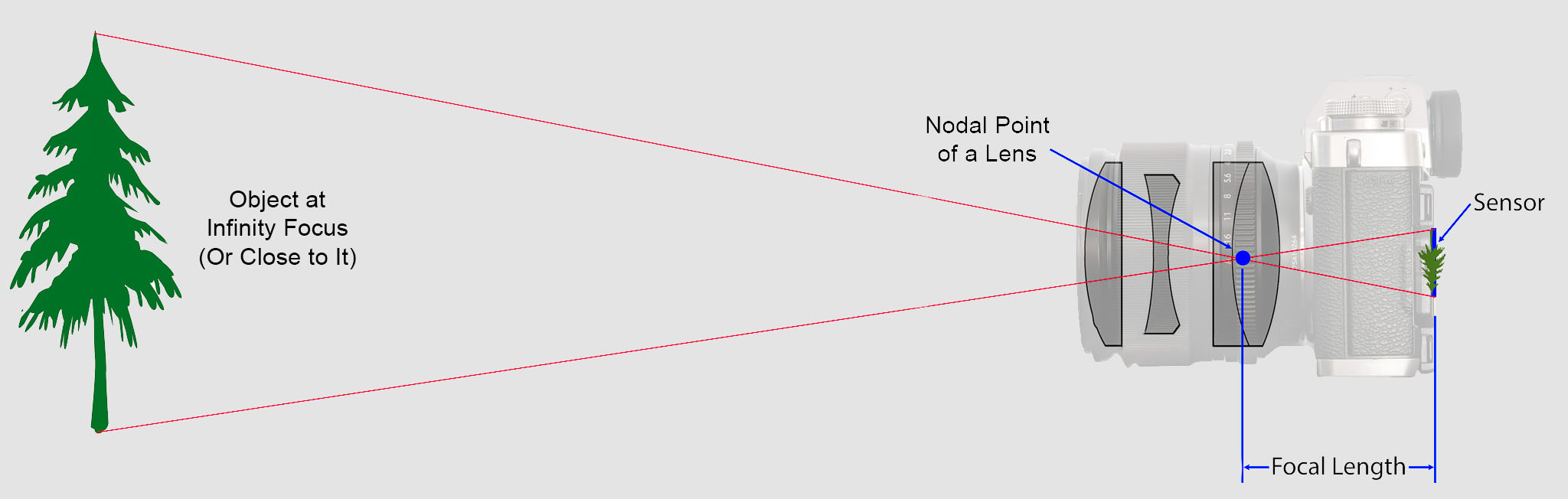
The focal length of an optical system is a measure of how strongly the system converges or diverges light.
Without getting into an in-depth physics discussion, the focal length of a lens is an optical property of the lens.
The exact definition is: Focal length measures the distance, in millimeters, between the “nodal point” of the lens and the camera’s sensor.
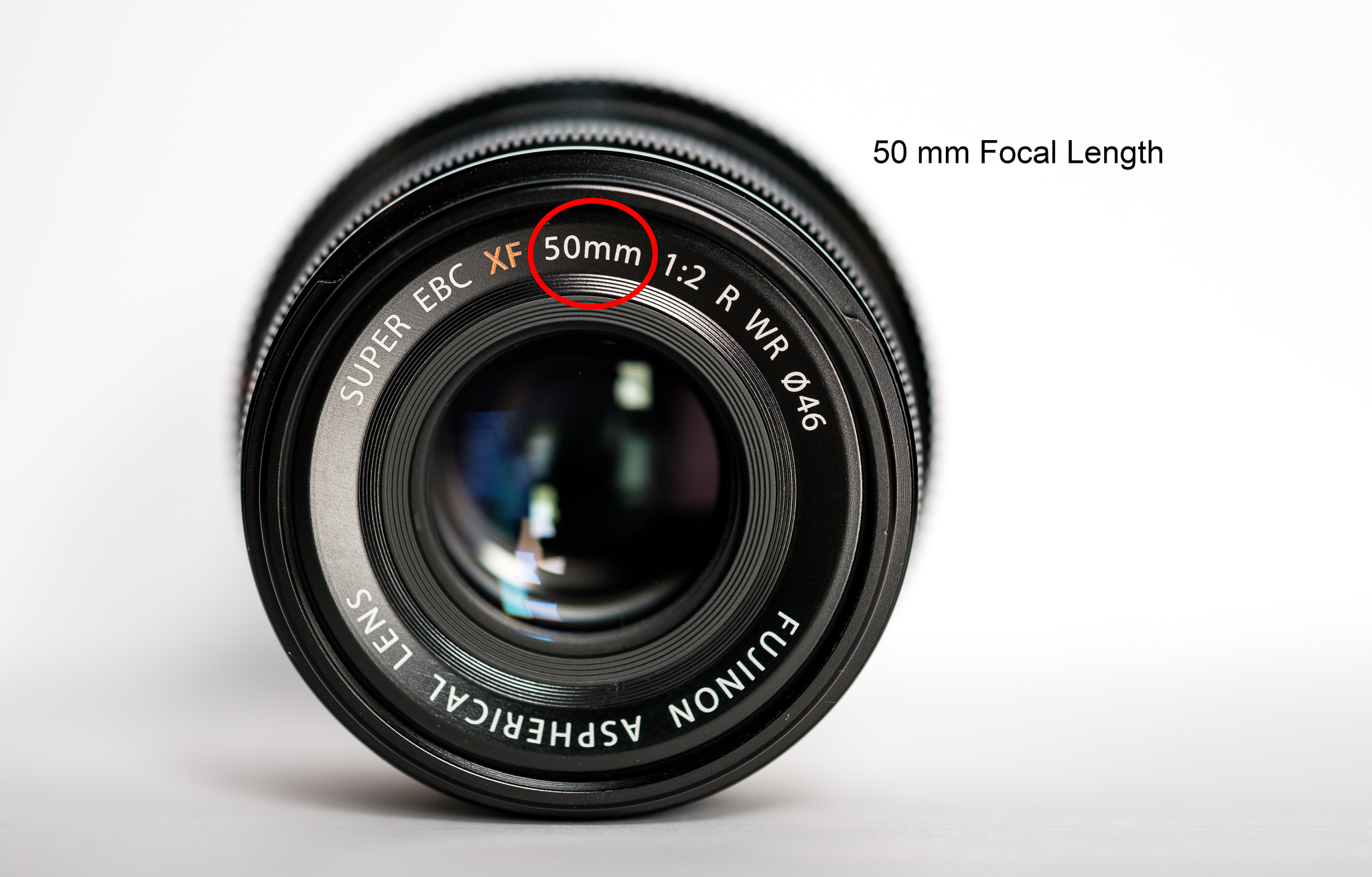
Lenses are named by their focal length. You can find this information on the barrel of the lens, and almost every camera lens ever made will prominently display the focal length. For example, a 50mm lens has a focal length of 50 millimeters.
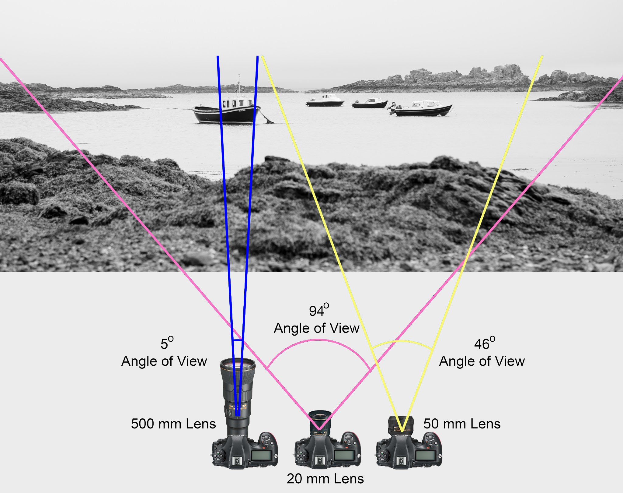
In most photography and all telescopy, where the subject is essentially infinitely far away, longer focal length (lower optical power) leads to higher magnification and a narrower angle of view;
Conversely, shorter focal length or higher optical power is associated with lower magnification and a wider angle of view.
On the other hand, in applications such as microscopy in which magnification is achieved by bringing the object close to the lens, a shorter focal length (higher optical power) leads to higher magnification because the subject can be brought closer to the center of projection.
Focal length is important because it relates to the field of view of a lens – that is, how much of the scene you’ll capture. It also explains how large or small a subject in your photo will appear.
FlexClip is an easy yet powerful video maker that helps you create videos for any purposes. Here are some of its key features:
* Millions of stock media choices (video clips, photos, and music).
* A clean and easy-to-use storyboard to combine multiple photos and clips.
* Flexible video editing tools: trim, split, text, voice over, music, custom watermark, etc.
* HD video export: 480P, 720P, 1080P.

The main limitation that our technology future forecasts is a challenge in speed while supporting valid data to the user base.
Generally speaking, data can change after being stored locally in various databases around the world, challenging its uber validity.
With around 75 billion users by 2030, our current infrastructure will not be able to cope with demand. From 1.2 zettabytes world wide in 2016 (about enough to fill all high capacity 9 billion iphone’s drives), demand is planned to raise 5 times in 2021, up to 31Gb per person.
While broadband support is only expected to double up.
This will further fragment both markets and contents, possibly to levels where not all information can be retrieved at reasonable or reliable levels.
The 2030 Vision paper lays out key principles that will form the foundation of this technological future, with examples and a discussion of the broader implications of each. The key principles envision a future in which:
1. All assets are created or ingested straight into the cloud and do not need to be moved.
2. Applications come to the media.
3. Propagation and distribution of assets is a “publish” function.
4. Archives are deep libraries with access policies matching speed, availability and security to the economics of the cloud.
5. Preservation of digital assets includes the future means to access and edit them.
6. Every individual on a project is identified and verified, and their access permissions are efficiently and consistently managed.
7. All media creation happens in a highly secure environment that adapts rapidly to changing threats.
8. Individual media elements are referenced, accessed, tracked and interrelated using a universal linking system.
9. Media workflows are non-destructive and dynamically created using common interfaces, underlying data formats and metadata.
10. Workflows are designed around real-time iteration and feedback.

Given a some level of omniscent entity or computer, future and past can be revealed at some level of probability.
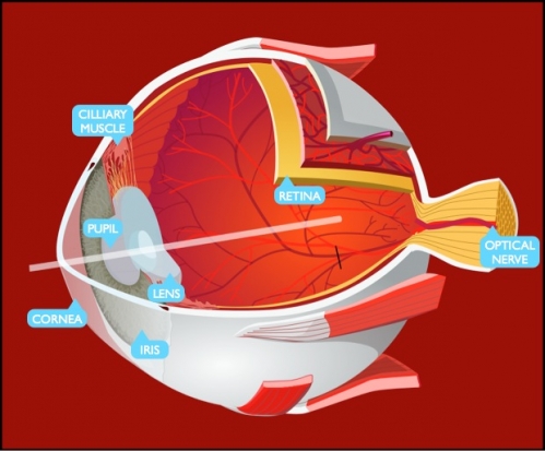
https://www.quora.com/What-is-the-comparison-between-the-human-eye-and-a-digital-camera
https://medium.com/hipster-color-science/a-beginners-guide-to-colorimetry-401f1830b65a
There are three types of cone photoreceptors in the eye, called Long, Medium and Short. These contribute to color discrimination. They are all sensitive to different, yet overlapping, wavelengths of light. They are commonly associated with the color they are most sensitive too, L = red, M = green, S = blue.
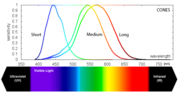
Different spectral distributions can stimulate the cones in the exact same way
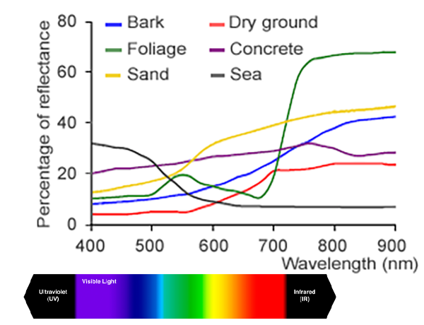
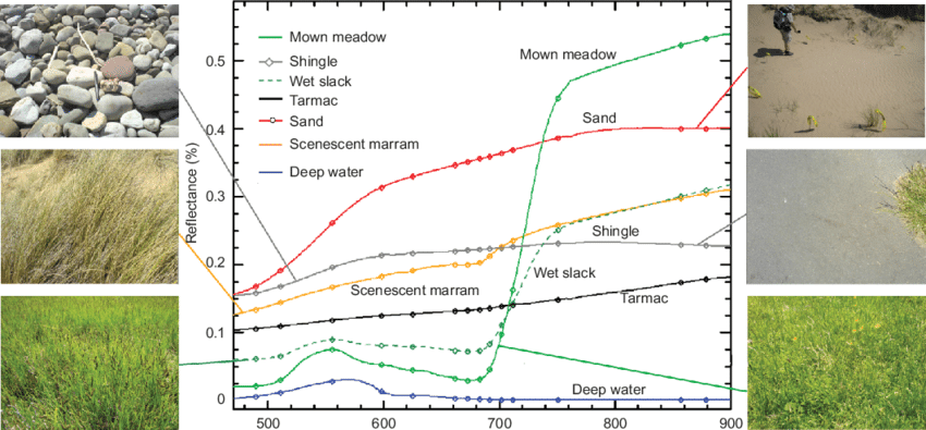
A leaf and a green car that look the same to you, but physically have different reflectance properties. It turns out every color (or, unique cone output) can be created from many different spectral distributions. Color science starts to make a lot more sense when you understand this.
When you view the charts overlaid, you can see that the spinach mostly reflects light outside of the eye’s visual range, and inside our range it mostly reflects light centered around our M cone.
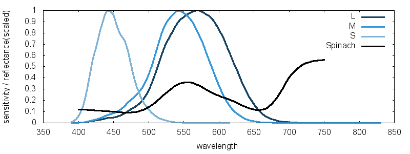
This phenomenon is called metamerism and it has huge ramifications for color reproduction. It means we don’t need the original light to reproduce an observed color.
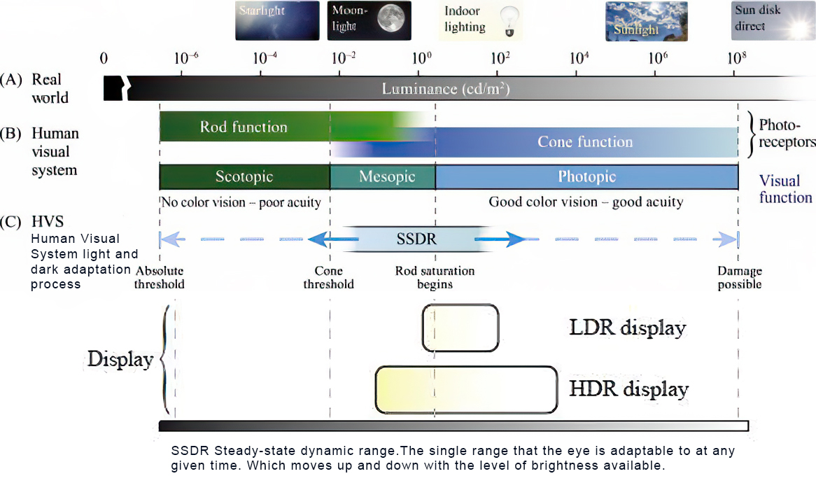
http://www.absoluteastronomy.com/topics/Adaptation_%28eye%29
The human eye can function from very dark to very bright levels of light; its sensing capabilities reach across nine orders of magnitude. This means that the brightest and the darkest light signal that the eye can sense are a factor of roughly 1,000,000,000 apart. However, in any given moment of time, the eye can only sense a contrast ratio of one thousand. What enables the wider reach is that the eye adapts its definition of what is black. The light level that is interpreted as “black” can be shifted across six orders of magnitude—a factor of one million.
https://clarkvision.com/articles/eye-resolution.html
The Human eye is able to function in bright sunlight and view faint starlight, a range of more than 100 million to one. The Blackwell (1946) data covered a brightness range of 10 million and did not include intensities brighter than about the full Moon. The full range of adaptability is on the order of a billion to 1. But this is like saying a camera can function over a similar range by adjusting the ISO gain, aperture and exposure time.
In any one view, the eye eye can see over a 10,000 range in contrast detection, but it depends on the scene brightness, with the range decreasing with lower contrast targets. The eye is a contrast detector, not an absolute detector like the sensor in a digital camera, thus the distinction. The range of the human eye is greater than any film or consumer digital camera.
As for DSLR cameras’ contrast ratio ranges in 2048:1.
(Daniel Frank) Several key differences stand out for me (among many):
COLLECTIONS
| Featured AI
| Design And Composition
| Explore posts
POPULAR SEARCHES
unreal | pipeline | virtual production | free | learn | photoshop | 360 | macro | google | nvidia | resolution | open source | hdri | real-time | photography basics | nuke
FEATURED POSTS
Social Links
DISCLAIMER – Links and images on this website may be protected by the respective owners’ copyright. All data submitted by users through this site shall be treated as freely available to share.